English
 العربية
 bosanski jezik
 Български
 Català
 粤语
粤语 中文(漢字)
 Hrvatski
 Čeština
 Dansk
Dansk Nederlands
 Eesti keel
 Suomi
Suomi Français
 Deutsch
 Ελληνικά
 עברית
עברית Magyar
 Italiano
 日本語
日本語 한국어
한국어 Latviešu valoda
 Bahasa Melayu
 Norsk
Norsk پارسی
پارسی Polski
 Português
 Română
 Русский
 Cрпски језик
 Slovenčina
 Slovenščina
 Español
 Svenska
 தமிழ்
தமிழ் ภาษาไทย
 Tiếng Việt


Návrh antény ovladače musí vzít v úvahu rozložení obvodu, ukazovací ovládání, provozní režim, modulární příslušenství, optimalizace signálu, atd. Ve stejnou dobu, různé aplikační scénáře, jako je satelitní komunikace, dálkové ovládání dronu, a ovládání motoru. Mohou existovat různé požadavky na konstrukci antény, které je třeba vysvětlit v kombinaci s konkrétními případy.
Je třeba věnovat pozornost požadavku uživatele nepoužívat výrazy jako např “podle výsledků vyhledávání”. Například, když mluvíme o zapojení obvodu, ukazovací ovládání, provozní funkce, modulární design, a dovednosti umístění jsou citovány.
Může být nutné uspořádat odpověď do několika částí: designové body, provoz a ovládání, příklady aplikací, a preventivní opatření. Například, body návrhu zahrnují uspořádání obvodu a ovládání polohování; ovládání a ovládání zahrnuje manuální/automatický režim a nastavení parametrů; příklady aplikací zmiňují dálkové ovládání dronů a satelitní komunikaci; opatření zahrnují stabilitu signálu a kompatibilitu příslušenství.
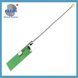
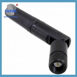 W24-ASMA-M 2,4 GHz WLAN, nakloněná RF anténa |
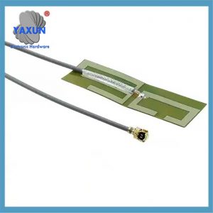
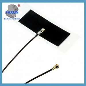 2065600100 1.561GHz, 1.575RF anténa s propojovacím kabelem pro povrchovou montáž GHz GPS |
 MB.TG30.A.305111 700 MHz, 850MHz, přímá RF anténa |
Návrh a aplikace řídicích antén zahrnuje několik dimenzí, jako je optimalizace hardwaru, ovládání signálu a provozní režim. Následuje shrnutí klíčových bodů:
I. Návrh hardwaru a optimalizace signálu
Specifikace uspořádání obvodu
Kabeláž pohonu brány musí být co nejširší a nejkratší (jako je 1oz měděný plášť odpovídá šířce 20mil) ke snížení ztráty odporu; vedení signálu hradla a uzlu spínače musí být blízko sebe, aby se snížilo indukční rušení.
Vyhněte se pravoúhlému vedení, a dát přednost tupému nebo obloukovému provedení, aby se zabránilo elektromagnetickému rušení (Emi) a aktuální problémy s reflexí.
Použijte technologii slzy k optimalizaci podložky a připojení ke zvýšení mechanické spolehlivosti a stability signálu.
Technologie ovládání ukazování
Dosáhněte vysoce přesného nasměrování antény pomocí kompenzace dopředné polohy a kompozitní strategie řízení, který je vhodný pro scénáře, jako je satelitní komunikace.
Ovladač gramofonu podporuje manuální/automatické přepínání režimů, lze nastavit rychlost (6-rozsah nastavení rychlosti) a jednokrokové/nepřetržité otáčení, a je vybaven funkcí nulování.
Modulární design
Elektricky nastavitelný anténní systém se skládá z ovladače (RET), ovladač (HCU/CCU), kabel AISG, atd., a podporuje rozšíření plug-in a přizpůsobení sdílení stránek.
Převádí elektrické signály z ovladače na rádiové vlny pro komunikaci s jinými zařízeními.
Dostávat:
Zachycuje rádiové vlny z jiných zařízení a převádí je zpět na elektrické signály, které může ovladač zpracovat.
Impedanční přizpůsobení:
Zajišťuje efektivní přenos energie mezi elektronikou ovladače a anténou, minimalizace ztráty signálu.
 Montáž ALA.01.07.00951,575GHz GPS PCB trasovací RF anténa |
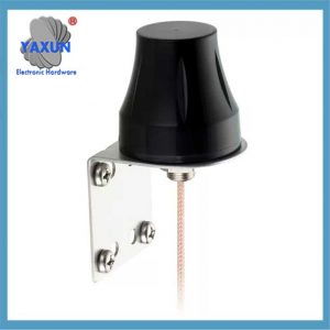 G30.B.108111.WM 829MHz WCDMA Dome RF anténa |
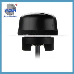 A.01.C.301111 1,575 GHz GPS Dome RF anténa |
II. Provoz a ladění bodů
Přepínání režimů a nastavení parametrů
Regulátor podporuje ruční ovládání (jednokrokové/nepřetržité otáčení, přepínání směru) a automatický reset, a upravuje rychlost, jednokrokový ekvivalent a další parametry prostřednictvím vizuálního rozhraní.
Ve scénářích dálkového ovládání, je nutné kombinovat antény WiFi/Bluetooth (jako jsou dvoupásmové gumové tyčové antény 2,4G/5,8G) pro zlepšení pokrytí signálem.
Optimalizace umístění antény
Externí antény se musí vyhýbat překážkám, a otevřené plochy by měly být nejprve opraveny (jako je upnutí okna nebo instalace přísavky).
Anténu dálkového ovládání dronu se doporučuje umístit svisle, a použijte charakteristiku všesměrového zisku ke zvýšení stability signálu.
Iii. Typické scénáře aplikací
Satelitní komunikace
Reléové satelity dosahují vysoce přesného sledování a přenosu dat letadel předběžným výpočtem trajektorií antény a technologií dynamické kompenzace.
Průmyslová zařízení
Super velké anténní gramofony (200kg zatížení) musí být sladěny s vyhrazenými ovladači pro podporu nastavení azimutu a ochrany proti přetížení za složitých pracovních podmínek.
Spotřební elektronika
Dálkové ovladače často používají prutovou anténu nebo externí prodlužovací kabel (jako je 3metrová anténa GPRS) přizpůsobit se scénám, jako jsou ovladače rolet a chytré domácnosti.
IV. Úvahy o výrobním designu:
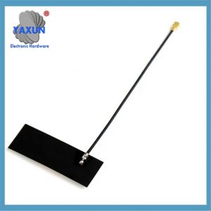
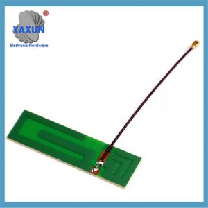
1. Typ antény:
Dipól/Monopol/Inverted-F: Běžné volby pro PCB antény, nabízí dobrý výkon a velikost.
Náplast: Jiný typ PCB antény, často se používá pro širokopásmové aplikace.
Čipové antény: Malý, nízkoprofilové antény, vhodné pro kompaktní zařízení.
Spirálové antény: Nabízí širší šířku pásma a může být navržen pro různé aplikace.
Mikropáskové antény: Populární typ tištěné antény, vhodné pro různé frekvence.
2. Velikost a tvar:
Určeno pracovní frekvencí, požadovaná šířka pásma, a prostorová omezení.
Větší antény mají obecně lepší výkon, ale také zvyšují velikost a náklady.
3. Materiál:
Materiál PCB: Nejčastěji se používá pro tištěné antény, poskytnutí vodivého povrchu pro prvky antény.
Kov: Používá se pro reflektory a další součásti antén.
Dielektrické materiály: Používá se k izolaci prvků antény a zajištění konstrukční podpory.
4. Impedanční přizpůsobení:
Zajištění, aby impedance antény odpovídala impedanci ovladače, zabraňuje odrazům signálu a maximalizuje přenos energie.
Dosaženo prostřednictvím odpovídajících sítí, ladicí prvky, nebo techniky impedančního přizpůsobení.
5. Rozložení a integrace PCB:
Pečlivé umístění prvků antény, napájecí linky, a zemní plochy pro minimalizaci rušení a optimalizaci výkonu.
Použití nástrojů CAD pro návrh a uspořádání antény k zajištění správné izolace a integrity signálu.
6. Testování a optimalizace:
Použití simulačních a měřicích nástrojů k vyhodnocení výkonu antény, jako je zisk, šířku pásma, a vyzařovací diagram.
Optimalizace konstrukčních parametrů antény pro dosažení požadovaných výkonnostních charakteristik.
7. Environmentální faktory:
Zohlednění faktorů prostředí, jako je teplota, vlhkost, a mechanickému namáhání, pro zajištění spolehlivého provozu antény.
Použití ochranných nátěrů nebo krytů ke zmírnění dopadu drsného prostředí.
 3G 4G anténa PCB Mount Antenna EMBED ASSY 185MM UFL |
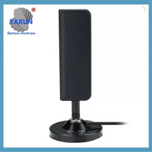
 Anténní příslušenství namontované ve vozidle 5G 4G LTE 3G 2.4G 2G |
 Přizpůsobená anténa dálkového ovládání, dětská elektrická anténa do auta |
PROTI. Opatření
Přizpůsobení frekvence: Výkon antény je výrazně omezen frekvenčním pásmem, a je třeba vybrat vhodný rozsah podle aplikace (jako např 80 metrů do 13 metrů pro lepší výkon).
Správa napájení: Některé ovladače se spoléhají na externí napájení (jako je č. 5 baterie), a dobíjecí baterie se doporučují pro prodloužení životnosti baterie1.
kompatibilita: Typ rozhraní přijímače (jako např “aktivní” rozhraní externí antény) a specifikace kabelů (jako je vnitřní kolík/vnější kolík SMA) je třeba potvrdit.
V podstatě, Výrobní návrh antény regulátoru je multidisciplinární proces, který zahrnuje pečlivé zvážení charakteristik antény, výběr materiálu, rozložení PCB, a optimalizace výkonu pro zajištění spolehlivé a efektivní bezdrátové komunikace.
Výše uvedený obsah shrnuje základní prvky antény řadiče v návrhu hardwaru, provozní logika a aktuální aplikace, a adaptační řešení je třeba vybrat na základě skutečných potřeb.