 English
 العربية
 bosanski jezik
 Български
 Català
 粤语
粤语 中文(漢字)
 Hrvatski
 Čeština
 Dansk
Dansk Nederlands
 Eesti keel
 Suomi
Suomi Français
 Deutsch
 Ελληνικά
 עברית
עברית Magyar
 Italiano
 日本語
日本語 한국어
한국어 Latviešu valoda
 Bahasa Melayu
 Norsk
Norsk پارسی
پارسی Polski
 Português
 Română
 Русский
 Cрпски језик
 Slovenčina
 Slovenščina
 Español
 Svenska
 தமிழ்
தமிழ் ภาษาไทย
 Tiếng Việt
Los vehículos eléctricos utilizan carga rápida y lenta, con carga rápida que emplea cargadores de CC de alta potencia para un reabastecimiento rápido, mientras que la carga lenta utiliza cargadores de CA durante más tiempo, carga más gradual en casa o en el trabajo.
Fast Charging:
Speed:
Offers significantly faster charging times compared to slow charging, allowing EVs to regain a substantial portion of their range in a short amount of time.
Fuerza:
Uses high-power DC chargers, typically delivering 50 kW or more, even exceeding 350 kW.
Infrastructure:
Requires specialized equipment and infrastructure, making it more suitable for public charging stations and commercial applications.
Aplicaciones comunes:
Ideal for long-distance travel and situations where quick top-ups are needed.
Battery Impact:
While fast charging can be convenient, frequent use may potentially degrade the battery faster due to the high power input and heat generated.
Charging Time:
Can charge the battery up to 80% capacity in as little as 30 minutos, but charging from 80% a 100% may take longer due to reduced charging speed for battery safety.
Slow Charging:
Speed: Characterized by longer charge times, A menudo se requieren horas para cargar completamente un vehículo eléctrico..
Fuerza: Utiliza cargadores de CA de menor potencia, normalmente van desde 3 kW a 22 kW.
Infrastructure: Más ampliamente disponible, especialmente para uso doméstico, y menos costoso y más fácil de instalar.
Aplicaciones comunes: Ideal para sesiones de carga nocturnas o prolongadas en casa, trabajar, u otros lugares donde el vehículo esté estacionado durante un período prolongado.
Battery Impact: Generalmente es más suave con la batería y puede ayudar a extender su vida útil..
Charging Time: Puede tardar varias horas en alcanzar una carga completa.
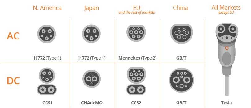
América del Norte, Japón, UE, China y resto de mercados Tipos de cargadores de vehículos eléctricos
Para vehículos de nuevas energías propulsados por baterías, La carga es una parte esencial.. Incluso si en el futuro puede haber servicios de reemplazo de baterías similares al repostaje de combustible., se estima conservadoramente que dentro de 10 años, Se deberá confiar en varias cargas rápidas y lentas para reponer energía de las baterías.. En esta ocasión les presentaré brevemente el sistema de carga de vehículos de nuevas energías..
El sistema de carga se puede dividir en dos métodos.: carga regular y carga rápida. A juzgar por la apariencia y el tamaño., la diferencia entre los puertos de carga es realmente muy simple. El puerto de carga rápida es grande y tiene 9 agujeros, y el puerto de carga lenta es pequeño y tiene 7 agujeros. De este modo, Incluso los usuarios novatos no cometerán errores.. Generalmente, Se diseñarán dos puertos de carga en la parte delantera y trasera del automóvil.. Algunos modelos también diseñarán dos puertos de carga juntos., como la parte delantera o trasera del coche. Los propietarios de automóviles pueden elegir el método de carga según sus necesidades de tiempo de carga..
Interfaz de carga rápida (carga rápida)
La carga rápida es un método de carga de CC. La corriente de carga debe ser mayor., que requiere la construcción de estaciones de carga rápida. No requiere que la batería esté completamente cargada., pero sólo satisface las necesidades de conducción continua. En este modo de carga, solo 50% a 80% de la batería se puede cargar en 20 a 30 minutos. La pila de carga terrestre (equipo) Emite directamente energía CC para cargar la batería del vehículo.. El vehículo eléctrico solo necesita proporcionar carga e interfaces de comunicación relacionadas..
Las ventajas de la carga rápida: corto tiempo de carga, rápido flujo de vehículos de carga, y ahorrar zona de aparcamiento en la estación de carga.
Desventajas de la carga rápida: menor eficiencia de carga, mayor fabricación de cargadores, costos de instalación y trabajo. La corriente de carga es grande y requiere alta tecnología y métodos de carga., Lo que tiene un impacto negativo en la vida útil de la batería.. It is easy to cause abnormalities in the power battery and pose safety risks. Además, high-current charging will have an impact on the public power grid and affect the power supply quality and safety of the power grid.
Regular charging (slow charging)
This charging mode is AC charging. The external power grid provides 220V civilian single-phase AC power to the electric vehicle on-board charger, and the on-board charger charges the power battery. It usually takes 5 a 8 hours to fully charge.
The advantages of ordinary charging: the charging pile (charging box) is low in cost and easy to install. The power grid’s low valley power at night can be used for charging to reduce charging costs. During the charging period, the charging current is small and the voltage is relatively stable, which can ensure the safety of the power battery pack and extend the service life of the power battery.
Disadvantages of ordinary charging: The charging time is too long and it is difficult to meet the needs of emergency operation of the vehicle.
Fast charging interface
DC+: DC power positive
DC -: DC power supply negative
Orina: Suelo (suelo)
S+: Communication CAN-H
S-: Communication CAN-L
CC1: Charging connection confirmation
CC2: Charging connection confirmation
A+: 12V+
A-: 12V-
difference between AC and DC of EV charging
How do you confirm whether CC1 and CC2 are connected properly?
The following is the CC1 charging pile connection detection schematic diagram.
As you can see from the chart below, to determine whether the connection is normal, you can confirm it by the voltage at the detection point. Different voltages are obtained by dividing voltage by different resistors.
Then there is the CC2 vehicle control device connection confirmation schematic diagram.
After it is turned on, the two resistors divide the voltage to obtain a voltage of 6V, otherwise a voltage of 12V is obtained.
Taking the BYD e6 as an example, the vehicle body connection device is used to conduct and input external electrical energy to the power battery when the vehicle is charging. The charging port cover has damping characteristics, eso es, check whether the resistance between “CC1” and “PE” on the charging port is 1KΩ; al mismo tiempo, you need to check whether the connection between the charging port and the power manager is normal.
Slow charging interface
CC: Vehicle control device connection confirmation
CP: Charging pile connection confirmation
Orina: Suelo (suelo)
L: Three-phase alternating current “U”
norte: Three-phase AC “neutral”
NC1: Three-phase alternating current “V”
NC2: Three-phase alternating current “W”
Normally NC1 and NC2 are empty.
L and N are the two wires connected to our household 220V.
How do CC and CP confirm whether the connection is normal?
The “cable control box” and the “vehicle control device” mutually confirm whether the connection is correct.
Primero, the “cable control box” will pass CP detection point 1 and detection point 4 to detect whether the voltage is 12V. If it is not connected properly, there will be no ground at detection point 4, and the voltage will not be detected. If the connection is good, detection point 4 is connected to the vehicle ground through PE, and the voltage is 12V at this time. After there is 12V power, the “cable control box” will connect S1 to PWM, otherwise S1 will be connected to +12.
Then, the vehicle control device will detect the R3 resistance through CC to confirm whether the charging gun is connected to the vehicle socket. Si no, the resistance will be infinite, otherwise there will be a corresponding resistance value.
Here, the vehicle control device will set the power of the on-board charger (usually set by the manufacturer by default):
The on-board charging device determines the maximum charging current of the control box on the cable through the duty cycle signal of CP. The general setting ratio is as follows:
Al mismo tiempo, the on-board charging device will also determine the rated capacity of the cable through the RC on the CC.
Finalmente, after calculating the rated capacity of the charging cable and the current of the control box on the cable, the vehicle control device sets the maximum power of the on-board charger to their minimum value.
Having said so much, some people must ask: “Why are there two charging interfaces? Isn’t it good to unify them into one?” This is mainly determined by fast charging.
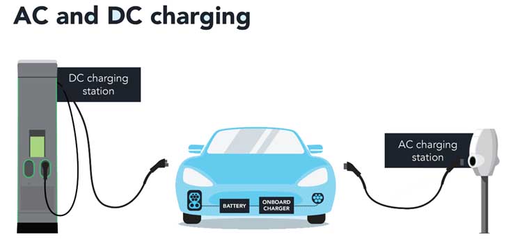
You must know that the charging process of a vehicle is not just from the power grid to the battery, but also requires passing through charging piles, charging cables, charging plugs, and vehicle socket interfaces before entering the vehicle. From the previous principles, we also know that for AC charging, after entering the vehicle, it does not go directly to the battery, but also passes through the two levels of on-board charger and BMS.
For fast charging, compared with AC charging, the charging power is not limited to the specific charging voltage and current, ranging from 20kW, 40kW, 60kW to 200kW, 250kW, and 350kW. As long as the input (grid) and output (vehicle) support it, it can be done very well.
The power from the grid first enters the charging pile and then reaches the vehicle through the charging cable. Most charging cables are fixed on the charging pile, and the other end is a gun-shaped plug connected to the vehicle (this connection method is called connection method C in the standard).
There are also a small number of charging piles that are isolated and require an independent cable, with both ends connected to the charging pile and the vehicle (connection method B). As for the way the charging cable is fixed on the vehicle (connection method A), it has almost no application. AC charging can use connection mode B and connection mode C. For AC charging current greater than 32A and DC charging, only connection method C can be used.
Since the vehicle’s power system is a DC system, when charging with AC, AC power cannot directly charge the battery. It needs to go through a component called an on-board charger (OBC, On-board Charger) to convert AC to DC and transform the voltage according to the command of BMS before supplying it to the battery.
In this car charger composition diagram, there are two core components-ACDC rectifier and DCDC transformer (power unit in the picture). The former is used to convert alternating current into direct current that is acceptable to the vehicle battery, and the latter is used to adjust the voltage of the direct current.
According to the BMS command, the charging current and voltage are dynamically adjusted to adapt to the charging needs of the battery at different stages. Por ejemplo, during constant current charging, as the battery power increases, the charging voltage also needs to increase. It is also responsible for converting low voltage and charging the 12V small battery.
During DC charging, the DC pile itself is an ACDC rectifier plus a DCDC transformer, which directly converts AC power outside the vehicle according to the needs of the BMS, replacing the role of the on-board charger. Por lo tanto, DC charging piles are also called off-board chargers.
