 English
 العربية
 bosanski jezik
 Български
 Català
 粤语
粤语 中文(漢字)
 Hrvatski
 Čeština
 Dansk
Dansk Nederlands
 Eesti keel
 Suomi
Suomi Français
 Deutsch
 Ελληνικά
 עברית
עברית Magyar
 Italiano
 日本語
日本語 한국어
한국어 Latviešu valoda
 Bahasa Melayu
 Norsk
Norsk پارسی
پارسی Polski
 Português
 Română
 Русский
 Cрпски језик
 Slovenčina
 Slovenščina
 Español
 Svenska
 தமிழ்
தமிழ் ภาษาไทย
 Tiếng Việt
이 기사 시리즈에서는, 테슬라 충전 포트 구조 설계의 변화를 간략하게 분석해보겠습니다., 주로 Model S/X에 적합한 충전 스탠드를 선택합니다. 2015 모델에 맞게 조정된 케이블 버전 3 ~에 2018 간략한 분석을 위해. 알루미늄 튜브 충전대 조립체는 공개되지 않았습니다.. 알루미늄 튜브 버전에 대한 기타 정보, 이전 글을 참조해주세요: Tesla - 충전 버스바 특허; 독특하고 끊임없이 진화하는.
이 기사를 통해 다시 돌아가 보겠습니다. 2015 그리고 그 시대의 모델 X를 기반으로 한 초기 Tesla 충전 인터페이스의 구조 설계를 간략하게 분석합니다.. 출발점으로 활용하세요.
다음 분석 및 텍스트가 포함된 사진은 아래 언급된 기술의 최종 양산 상태를 나타내지 않습니다.. 아래 언급된 기술의 보편적이거나 우발적인 상황을 나타내지는 않습니다., 단순한 분석과 토론일 뿐이다..
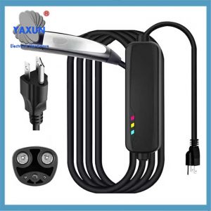 48레벨 1용 Nacs 플러그 케이블이 포함된 Tesla 연장 코드용 110-240V 6미터&2 EV 충전기 및 Tesla 벽면 커넥터 |
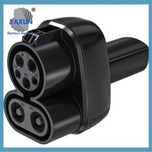
 NACS에서 NEMA로 5-20/15 NACS 벽면 커넥터와 호환되는 Tesla-nema 어댑터용 Pluge EV 어댑터 플러그 |
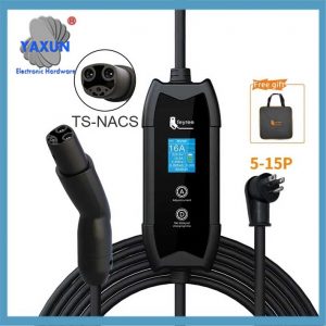
 1000V 250A Tesla 충전 플러그 교체 250KW NACS 충전 케이블 제조업체 |
소켓 전체 & 전력 설계
Tesla NACS 인터페이스 SOP 첫 번째 버전의 특징은 다음과 같습니다.:
● 초음파 용접 연결 와이어 및 단자는 최초로 V2 충전 요구 사항을 충족합니다. (후속 반복은 V3 수준에 가까워질 것입니다.);
● 90° 배출구 & 나사 잠금 터미널;
● 탈부착 가능한 보호 커버 (사고 방지 제거 기능이 있는);
● 다채로운 조리개 및 광원 시각적 디자인;
● 접지선은 단면적이 작습니다. & AC와 DC는 동일한 인터페이스를 공유합니다.;
● 신호 + PE 플러그인과 소켓 분리 가능;
동시에, 차량 충전 등의 기능, 총을 꺼내다, 뚜껑을 여는 것도 당시로서는 최첨단 디자인이었습니다.
차량 배치 위치 (모델 X)
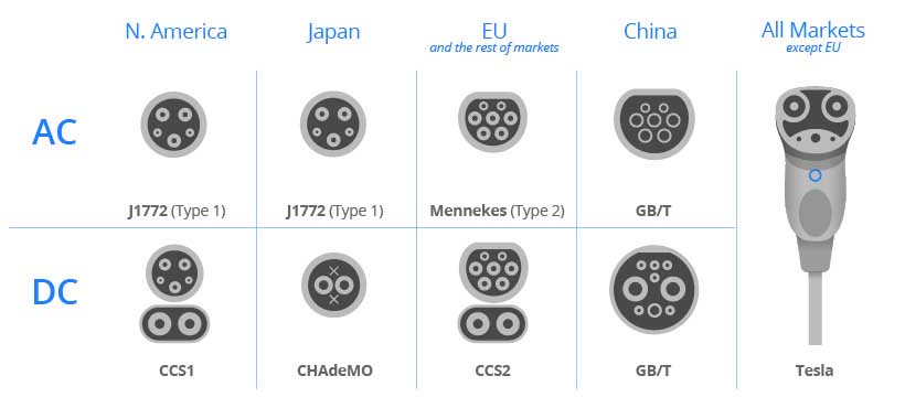
전체 패널 크기는 CCS보다 작습니다. & GB AC 및 DC 통합. 플러그인 부분의 크기와 충전 로직에 대한 자세한 내용은, 이전 기사를 참조하세요: Tesla 과충전에 대한 일부 데이터.
충전 소켓 조립 세부정보 (모델 X)
SOP 첫 번째 버전의 가장 큰 특징은 현재의 알루미늄 파이프와 유사합니다.. 콘센트 위치 보호는 충전대 자체에 의존하지 않습니다.. 꼬리 부분의 탈착식 보호 커버 + 90° 와이어 하네스 조립 및 유지 관리의 편의성을 높이기 위한 콘센트는 오늘날에도 그대로 유지됩니다., 행/막대/튜브 도체 제품은 현재 점점 더 대중화되고 있습니다.. 점점 더 많은 BMK 제조업체가 있습니다.
충전소켓 조립개구커버 상세정보
게다가, 전반적인 디자인 요구 사항으로 인해, 신호 + PE 플러그인은 부드럽고 단단한 접착제와 통합되어 있습니다. + 철사 + 단말기. 동시에, 버클을 소켓에 조립한 후, 탈착식 보호 커버를 사용하여 CPA와 유사한 기능을 구현할 수 있습니다., 그것은 또한 배울 가치가 있다. 일체형 성형품을 완전히 조립한 후 약간의 흔들림이 있습니다..
충전 소켓 어셈블리 외부 인터페이스 및 신호 세부정보
파워 디자인 측면에서, 초기 단계에서, 통조림 구리 + 저전력 충전을 위해 압착 기술을 사용했습니다. (현재 고출력 충전의 최대 전력 대비). 나중에, 순수 구리 + 초음파 용접 및 알루미늄 와이어 + 초음파 용접이 사용되었습니다., 하지만 변하지 않은 것은 위에서 언급한 단자와 케이블의 보호 설계입니다.. 전선이 지속적으로 업그레이드되는 동안, 보호가 업그레이드되지 않았습니다. 과거와 현재를 보면, 알루미늄 도체의 보호 없는 종단 설계를 탐구해야 합니까?? 졸겔코팅 등.
미국 시장은 EV 플러그 디자인에서 Tesla를 따릅니다.
충전 소켓 어셈블리의 초음파 용접:
차폐 처리 측면에서, 어떤 이유로 인해, Model X와 S는 각각 소켓 끝 차폐 열 수축 튜브를 선택하여 단일 끝 서스펜션과 차폐 압착을 감싸고 본체 판금을 이중 끝 접지에 연결합니다.. 이후에도 유사한 교차 선택 상황이 있습니다. 2018 모델 3 현재의 알루미늄 튜브 솔루션. 더 높은 충전 전력에서 차폐 효과를 구현하려면 추가 연구가 필요합니다..
충전 소켓 어셈블리 차폐 처리:
성능면에서, 초음파 용접 및 낮은 종단 저항 덕분에, 전류 아날로그 충전은 공냉식 환경에서 오랜 시간 동안 전류 전달을 최대 전력으로 유지할 수 있습니다..
접지 설계는 이전과 같습니다., 도체 단면적은 대부분의 DC 인터페이스 설계보다 작습니다., 충전 인터페이스가 차지하는 공간을 크게 줄입니다., 접지는 차량용 충전기용으로 설계되었습니다..
충전 소켓 어셈블리 접지 구멍 및 기타:
다채로운 조리개 + 균일한 그라데이션 색상, this is also a relatively excellent sensory experience at present. The overall design is centered on the tail pin limiting plate. Two layers of translucent plastic parts project the light source on the PCBA to the light-transmitting position of the charging port, achieving uniform light distribution in the forward viewing area.
In other examples of different interfaces at the same time, different aperture design positions are achieved by changing the position of translucent plastic. This is also the advantage of standardized aperture design.
Charging socket assembly aperture visualization
But the light assembly is built into the charging socket. There are areas that need constant adjustment in the entire socket manufacturing and vehicle matching of new models (perhaps cost is also one of the key points). In subsequent Model 3/Y models, the lighting module in the charging socket assembly is moved out of the socket body and placed in the socket connection plate, often with the Tesla LOGO.
Partial PCBA and Pin of charging socket assembly
Compared with GB IEC and other AC and DC integrated solutions. The first version of Tesla NACS SOP signal and ground output uses 6Pin plug-in (1Pin reserved) * 1 + Pilot * 1 + ground terminal * 1 + Prox * 1 (PE is integrated with Pilot and Prox). The overall simplified low-voltage loop output reduces the number of wire harness assemblies and reserves space for subsequent PCBA and panel miniaturization. Subsequent requirements for temperature monitoring and other aspects will continue to increase. Tesla’s latest NACS is 12+3Pin (including plug-in locking lock, except for some Model Gun lock), CCS is 12+3 핀 (including gun lock).
Current standard charging socket assemblies
Regarding the arrangement of the locking lock of the insertion gun, NACS has been at the bottom of the socket since the first version of the SOP to the current version, and the drainage is arranged together. It is good for drainage, but the ability of the entire lance lock to resist the intrusion of debris is weaker than other standard interfaces (it occasionally fails here). 현재, the aluminum tube solutions of most vehicle models abandon the first version of the SOP lock design and adopt solutions with a better protection level.
The mounting plate screws are all self-tapping screws, 4 in total.
Charging socket assembly secondary BOM failure mode
Early versions always have a lot of failure modes. Some failure modes have been circumvented, and some failure modes currently persist. The following is a brief analysis of a structural design failure.
Failure mode: Anti-touch cap falls off. This failure mode occurs when the terminal is turned. Due to the special nature of the subsequent punching and rounding processes, the risk of falling off is greater than before. In addition to Tesla, other OEMs have also experienced similar problems.
Charging socket assembly failure mode
To minimize the risk of failure, during the early stage of refined dimensional design and multi-dimensional verification, changing the anti-touch finger and terminal connection methods can also be taken into consideration.