 English
 العربية
 bosanski jezik
 Български
 Català
 粤语
粤语 中文(漢字)
 Hrvatski
 Čeština
 Dansk
Dansk Nederlands
 Eesti keel
 Suomi
Suomi Français
 Deutsch
 Ελληνικά
 עברית
עברית Magyar
 Italiano
 日本語
日本語 한국어
한국어 Latviešu valoda
 Bahasa Melayu
 Norsk
Norsk پارسی
پارسی Polski
 Português
 Română
 Русский
 Cрпски језик
 Slovenčina
 Slovenščina
 Español
 Svenska
 தமிழ்
தமிழ் ภาษาไทย
 Tiếng Việt
Perbandingan menyeluruh kimpalan ultrasonik dan abah-abah pendawaian pengelim jenis U
I. Prinsip kerja
Kimpalan ultrasonik
Melalui getaran mekanikal frekuensi tinggi (biasanya 20kHz atau 40kHz), permukaan sentuhan logam digosok untuk menghasilkan haba, dan pelakuran molekul dicapai dalam keadaan pepejal. Ia tergolong dalam teknologi kimpalan fasa pepejal. Tiada sumber haba semasa atau suhu tinggi diperlukan untuk mengelakkan masalah pengoksidaan dan percikan.
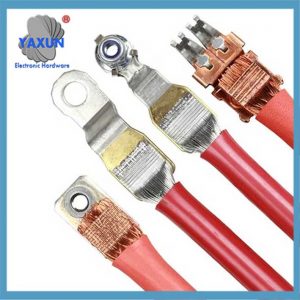
 Terminal Tembaga Bentuk U Kabel Kawat Kelim Tong Terbuka Pendawaian Pantas Punggung Dok Penyambung Kit Pelbagai Kit |
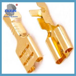 Penyambung Abah-abah Pendawaian Kereta Jenis U Berkualiti Tinggi Tembaga Loyang Kelim Terminal Bersama untuk Kabel 6-10mm2 |
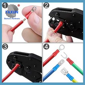 Kit Pelbagai Penyambung Elektrik Wayar dengan Cincin, Spade, Punggung, Putuskan sambungan, Kelim Wire Harness |
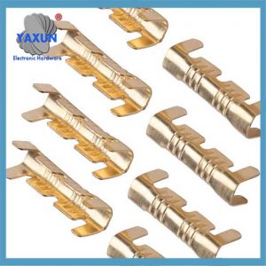
Kelim jenis U
Pengecapan sejuk beberapa wayar menggunakan terminal berbentuk U, sambungan mekanikal melalui geseran yang dihasilkan oleh ubah bentuk fizikal. Prosesnya mudah sahaja, tetapi mungkin terdapat rongga kecil di dalamnya kerana ubah bentuk yang tidak mencukupi.
Iii. Proses dan kos
Pelaburan peralatan
Kos awal mesin kimpalan ultrasonik adalah tinggi (kepala kimpalan khas dan pelarasan parameter berketepatan tinggi diperlukan), tetapi kos penyelenggaraan jangka panjang adalah rendah; Peralatan pengelim jenis U mempunyai kos yang rendah, tetapi terminal dan acuan perlu diganti dengan kerap.
Kecekapan pengeluaran
Kimpalan ultrasonik mempunyai kelajuan yang pantas (<1 kedua/titik), yang sesuai untuk pengeluaran besar-besaran; Pengeliman jenis U memerlukan bantuan manual untuk melaraskan kedudukan wayar, dan kecekapannya lebih rendah sedikit.
Keperluan bahan
Kepala kimpalan ultrasonik memerlukan aloi khas dengan rintangan haus yang tinggi (seperti aloi titanium), dan proses pembuatan adalah kompleks; Terminal berbentuk U kebanyakannya adalah aloi tembaga atau aluminium, dengan tahap standardisasi yang tinggi.
Iv. Perlindungan dan keselamatan alam sekitar
Kimpalan ultrasonik tidak mempunyai percikan api, tidak memerlukan pateri atau fluks, dan selaras dengan trend pembuatan hijau;
Kelim berbentuk U bergantung pada ubah bentuk fizikal, dan walaupun ia tidak mempunyai pelepasan, ia memerlukan rawatan sisa logam.
V. Senario aplikasi biasa
Kimpalan ultrasonik yang diutamakan:
Abah-abah pendawaian voltan tinggi untuk kenderaan tenaga baharu, talian komunikasi on-board (seperti bas CAN), abah-abah pendawaian sensor ketepatan, dan bidang lain yang mempunyai keperluan ketat untuk rintangan rendah dan kebolehpercayaan yang tinggi. Kelim berbentuk U yang diutamakan:
Abah-abah pendawaian voltan rendah biasa, abah-abah pendawaian kenderaan kos rendah, dan senario pembaikan sementara.
Ringkasan
Kimpalan ultrasonik mempunyai lebih banyak kelebihan dalam prestasi, ketahanan, dan perlindungan alam sekitar, tetapi kosnya lebih tinggi; Kelim berbentuk U terkenal dengan ekonomi dan fleksibilitinya, dan sesuai untuk senario konvensional. Pemilihan sebenar perlu dinilai secara menyeluruh dalam kombinasi dengan keperluan proses tertentu, belanjawan kos, dan kedudukan produk.
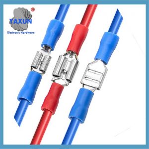 Garpu U-Jenis Tertebat Set Terminal Merah-Biru Set Kabel Wayar Elektrik Kelim Penyambung Gelang Spade |
 Terminal kimpalan logam ultrasonik dengan kelim penebat – Mesin Kimpalan erminal, Mesin Stripping dan Crimping |
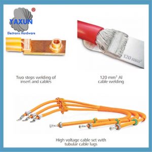 Nilai Bersih Proses Kimpalan Logam Ultrasonik |
Kimpalan ultrasonik dan pengelim berbentuk U digunakan secara meluas dalam syarikat sebagai dua kaedah utama untuk menyambung wayar abah-abah pendawaian kereta.. Jurutera abah-abah pendawaian artikel ini terutamanya memperkenalkan dua kaedah sambungan antara wayar, kimpalan ultrasonik dan pengeliman berbentuk U, dalam pengeluaran dan pembuatan abah-abah pendawaian automotif. Analisis perbandingan kebaikan dan keburukan kedua-dua kaedah ini telah dijalankan, yang boleh memberi rujukan untuk pemilihan kaedah penyambungan antara wayar dalam proses pengeluaran abah-abah pendawaian kereta..
Memandangkan fungsi peralatan elektrik automotif menjadi semakin kompleks, dan semakin banyak jenisnya, abah-abah pendawaian berfungsi sebagai medium untuk penghantaran isyarat antara pelbagai peralatan elektrik di dalam kereta. Hubungan gelung antara wayar abah-abah wayar menjadi semakin kompleks, dan semakin banyak tempat daftar masuk antara wayar. Contohnya, terdapat beratus-ratus mata tersangkut dalam abah-abah pendawaian teksi trak tugas berat.
Oleh itu, proses tebukan adalah bahagian yang sangat penting dalam proses pengeliman abah-abah wayar. Isu-isu seperti pemilihan kaedah tebukan dan pemilihan peralatan tebukan mesti dipertimbangkan oleh pereka proses abah-abah wayar dan juga pengeluaran syarikat.
1 – Kaedah utama dan pengenalan daftar masuk abah-abah pendawaian kereta
Dalam industri abah-abah pendawaian automotif, punching refers to connecting the exposed copper wires after stripping off the insulation of each wire by welding or crimping to form a loop. The stuck point refers to the position where each wire harness is stuck. According to the position of the stuck point between the wires, the punching method can be divided into opening punching and docking punching.
Open punching means that the main line is a whole conductor and the clamping point is on the main line but not at both ends of the main line. The remaining wires are welded at the position where the main wire’s insulation is stripped off, so it is also called mid-stripping punch.
Butt punching means that the clamping point is at the end of the wire, and one end of the wire is connected to one end of other wires that need to be punched through crimping or welding. It can be one conductor and multiple conductors, or two or more conductors and multiple conductors. The wires in which both ends are involved in punching are called transition wires. Single-side punching is a special way of butt punching, itu, all wires are welded or crimped on the same side. The opening punch-in and docking punch-in are shown in Figure 1.
Rajah 1, Schematic diagram of wire stripping and docking.
Depending on the equipment and principles, punching can be divided into two types: ultrasonic welding and U-shaped parts crimping.
Ultrasonic welding is a welding method that uses high-frequency mechanical vibration to recombine the surface of the welding material. It is a process between cold pressure welding and friction welding. It converts low-frequency electricity into high-frequency electricity, then converts high-frequency electrical energy into high-frequency mechanical vibration energy, and then transmits the high-frequency mechanical vibration energy to the surfaces of the two metals that need to be welded. And apply a vertical pressure on the welding surface, causing the two metal surfaces to rub against each other to generate heat energy to melt the metal, and under the short pressure, the melt will form a fusion between the molecular layers when the bonding surface solidifies.
The principle of ultrasonic welding is shown in Figure 2. For U-shaped parts crimping, the U-shaped parts and crimping machine are selected based on the total wire diameter of the contacts. A special crimping die and jaws are developed for each type of U-shaped piece, and then two or more wires are cold-stamped together with the help of U-shaped piece crimping equipment. U-shaped piece crimping is a simple physical squeeze of the copper wire of the wire through the U-shaped part of the metal piece, and the surface friction between adjacent copper wires is used to ensure the connection between the wire and the U-shaped piece.
Rajah 2 Schematic diagram of ultrasonic welding principle
2 – Comparative analysis of ultrasonic welding and U-shaped parts crimping
2.1 Comparative analysis of conductive properties
Voltage drop is an important indicator of the conductive performance of a wire. The so-called voltage drop refers to the potential difference formed across the resistor when current flows. According to Ohm’s law U=RI, when the current of the circuit is constant, the voltage is proportional to the resistance, itu, the larger the resistance, the greater the voltage drop, and the smaller the resistance, the smaller the voltage drop. The voltage drop U of an insulated conductor is calculated as:
U=IPL/A
(1) Dalam formula, U—voltage drop; P—resistivity; L—wire length; A—wire cross-sectional area.
U-shaped crimping is a simple extrusion of the copper wire of the conductor to cause physical deformation of the copper wire to create a connection through friction. Adjacent copper wires in the wire are still independent metal entities and cannot be in complete contact to form holes. The existence of these voids is inevitable, which will cause the resistivity P of the crimping part to increase, the voltage drop U to increase, and the conductivity to decrease, thereby reducing the transmission quality of electrical signals. Affect the normal operation of electrical and electronic equipment. After ultrasonic welding, the adjacent metals are fused into a whole, which results in a better density than the welding part of U-shaped parts. There will be no voids, the resistivity is low and close to zero, the voltage drop of ultrasonic welding is lower under the same conditions, and the conductivity and signal transmission quality are better. Di samping itu, the ultrasonic welding part has a lower resistance than the U-shaped part crimping, which reduces the heat accumulation caused by contact resistance. To a certain extent, the quality hazard of wire harness burning caused by the local temperature increase of the wire harness is avoided.
2.2 Comparative analysis of usage scope
Ultrasonic welding is very effective in improving the signal transmission quality and current transmission capacity of wires, and can also improve the stability of automobile electrical systems. Contohnya, wires with a cross-sectional area of 10 mm2 or more and Controller Area Network (Boleh) wires generally require ultrasonic welding. Walau bagaimanapun, ultrasonic vibration will destroy the coating. Copper surface coatings such as silver plating, zinc plating, tin plating, dll. can prevent oxidation and improve conductivity. Tin plating of copper wire has a great impact on ultrasonic welding. The melting points of tin and copper are very different. During welding, the tin layer is quickly in a molten state, thus blocking the combination of copper atoms and affecting the welding quality. For coated wires, U-shaped crimping is generally required.
2.3 Comparative analysis of welding quality
Ultrasonic welding materials have metal properties that are non-melting and non-brittle, and are minimally affected by external moisture, dust, oil and gas. It is not easy to cause corrosion, oxidation and other undesirable conditions in the copper wire, thereby avoiding the degradation of wire harness conductivity and signal transmission performance, and the reliability of stuck connection is high. There are residual stresses in the wire core at the crimping part of the U-shaped parts, and there is a risk of metal stamping rebound, and there is a risk of oxidation and rust under harsh working conditions. Not as reliable as ultrasonic welding. Ultrasonic welding has a rectangular shape at the welding point, with no loose core wires, broken ends or cracked core wires, and the wires are not bent and lead out straight from the fusion point. Ultrasonic welding may cause excessive welding flash and pierce the protective heat-shrinkable tube; the end of the wire core extends to overlap the wire insulation layer; the wire does not come out in a straight line from the fusion point; the wire core flies out and pierces the protective heat-shrinkable tube. A defective product caused by one or more broken core wires due to the welding process (generally, it is required that the number of missing core wires for each wire does not exceed 10%). When U-shaped parts are crimped, the wire core may fly out and pierce the protective heat shrink tube; the end of the wire core stretches to overlap the wire insulation layer; the wire sheath is pressed by the punching piece; the total diameter of the punching wire does not match the punching piece, dll.
2.4 Comparative analysis of costs
Ultrasonic welding requires metal materials with good toughness (small mechanical loss during sound wave transmission). Oleh itu, the most commonly used materials are aluminum alloy and titanium alloy. Walau bagaimanapun, ultrasonic metal welding requires the welding head to be wear-resistant (higher hardness is required), which makes the selection of materials more difficult, because hardness and toughness are inherently opposed, which requires the selection of very high-quality steel materials. To maximize the effective life of the welding head, the cost is very high. The price of ultrasonic welding machines is generally higher than that of crimping machines, and the initial investment is higher. When using U-shaped crimping, a U-shaped piece is required for each clamping point in the harness. Wire harness products with many stuck points and large batches use a large number of U-shaped parts, resulting in high cumulative costs. Contohnya, the price of U-shaped parts is 0.05 RMB/piece, and the number of cab wiring harness clamping points is 100 pieces/hanging, then the total cost of producing 1,000 cab wiring harness U-shaped parts is 5,000 RMB.
2.5 Comparative analysis of operability
Before ultrasonic welding and U-shaped parts crimping, it is necessary to sort out the stripped copper wires of the welded wires to avoid problems such as warped copper wires, burrs, scattered copper wires, and contamination with foreign matter.
During the ultrasonic welding process, the wires should be arranged vertically overlapping, and the large cross-sectional area wires should be close to the welding tool head below to ensure sufficient welding. The conductors should be placed against the anvil surface, snugly against each other, to provide sufficient solidity after welding. The length of conductor overlap should generally be between 5 mm and 7 mm. If the overlapping length is too short, it is difficult to ensure the welding strength. If the overlapping length is too long, the welding end will easily become warped, making it inconvenient for the next process. Oxidation, broken wires, defects and melting of the insulation layer are generally not allowed on the surface of the welding joint. The schematic diagram of ultrasonic welding operation is shown in Figure 3.
Rajah 3, Schematic diagram of ultrasonic welding operation
U-shaped parts crimping production is fast and the equipment is simple. In principle, the number of crimped wires for U-shaped parts should not exceed 5. The recommended stacking order of wires is from thick to thin and from top to bottom. The conductor should be fully pressed into the crimped portion of the punch piece. The wire ends should be visible on both sides of the U-shaped piece and the length (C) from the insulation to the punching piece should not be greater than 3 mm, and the length of the wire core extending out of the punching piece should be 0≤B≤1 mm. The schematic diagram of the U-shaped component crimping operation is shown in Figure 4.
Rajah 4, U-shaped parts crimping operation schematic diagram
3 – Summary
Ultrasonic welding has lower resistivity, smaller voltage drop, better electrical conductivity and higher reliability than U-shaped parts crimping, but it requires a large investment in equipment, the welding head is more expensive, and it cannot weld plated metals. U-shaped parts crimping has a wider range of applications than ultrasonic welding, and the equipment is simple and easy to operate. Walau bagaimanapun, U-shaped parts use a lot of consumables. Compared with ultrasonic welding, U-shaped parts have higher resistivity, larger voltage drop, poorer conductivity, and poorer reliability. . Automotive wiring harness manufacturers should conduct a comprehensive evaluation of these two wire connection methods and make reasonable configurations. Walau bagaimanapun, ultrasonic welding, as a new advanced welding technology, has obvious advantages such as superior conductivity and environmental protection, and is the development direction of automotive wire harness manufacturing.