 English
 العربية
 bosanski jezik
 Български
 Català
 粤语
粤语 中文(漢字)
 Hrvatski
 Čeština
 Dansk
Dansk Nederlands
 Eesti keel
 Suomi
Suomi Français
 Deutsch
 Ελληνικά
 עברית
עברית Magyar
 Italiano
 日本語
日本語 한국어
한국어 Latviešu valoda
 Bahasa Melayu
 Norsk
Norsk پارسی
پارسی Polski
 Português
 Română
 Русский
 Cрпски језик
 Slovenčina
 Slovenščina
 Español
 Svenska
 தமிழ்
தமிழ் ภาษาไทย
 Tiếng Việt
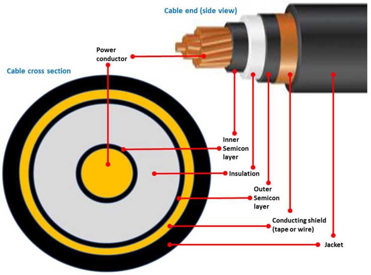
The composition of the high-voltage cable shielding layer mainly includes the conductor shielding layer, the insulation shielding layer and the metal shielding layer. The specific structure is as follows:
1. Conductor shielding layer (inner shielding layer)
Material properties
It is composed of semi-conductive materials (such as semi-conductive cross-linked polyethylene or semi-conductive polymers), which are in direct contact with the conductor and maintain the same potential, and are used to uniform the electric field on the conductor surface and reduce local discharge.
Position and function
It is located between the conductor and the insulation layer, filling the gaps or burrs that may exist on the surface of the conductor to avoid insulation damage caused by electric field concentration.
This consists of a layer of tightly woven wires, typically made of tinned copper, that surrounds the insulation.
Aluminum Foil Tape Shield:
This involves a thin layer of aluminum foil, often laminated to a polyester or polypropylene film, that provides a nearly 100% coverage of the insulation.
Semi-conducting Layers:
These layers, often made of semiconducting polymers, are placed between the conductor and insulation, and between the insulation and metallic shield. They help to evenly distribute electric stress and prevent partial discharges.
Purpose of Shielding Layers:
Electromagnetic Shielding:
The metallic shield acts as a Faraday cage, reflecting electromagnetic radiation and preventing interference from external sources and from the cable itself radiating noise.
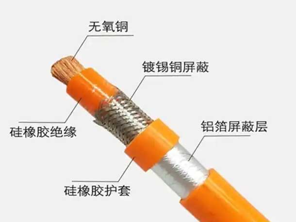
Silicone rubber insulation, tinned copper shield, silicone rubber sheath and aluminum foil shield
2. Insulation shielding layer (outer shielding layer)
Material and structure
It also uses semi-conductive materials, covers the outer surface of the insulation layer, and has the same potential as the metal sheath or armor layer to prevent local discharge caused by poor contact between the insulation layer and the sheath.
Function
Optimize the electric field distribution on the surface of the insulation layer and suppress the spread of electromagnetic interference (Эми) outward.
3. Metal shielding layer
Composition form
Metal tape/wire shielding: Commonly copper tape wrapping or tinned copper wire braiding, with a coverage rate of ≥85%;
Composite shielding structure: such as aluminum foil + braiding layer combination (aluminum foil prevents high-frequency interference, and the braiding layer enhances mechanical strength).
Additional function
It has both short-circuit current discharge and grounding protection functions, especially in extruded insulated cables without metal sheaths.
4. Other shielding designs (special scenarios)
Some high-voltage cables will add a semi-conductive buffer layer outside the metal shielding layer to alleviate the damage of mechanical stress to the shielding layer.
The benefits of using shielding layers for high-voltage wire harnesses and high-voltage connectors.
The shielding layer of high-voltage cables is divided into shielding wire braiding layer and aluminum foil layer. The conventional shielding layer structures are:
① Shield wire braid only
② Shielding wire braid (close to the inner insulation layer) + aluminum foil layer (close to the outer insulation layer)
③ Three states: aluminum foil layer (close to the inner insulation layer) + shielding wire braiding layer (close to the outer insulation layer).
Конечно, some high-voltage conductors use braided mesh, aluminum tubes, or a combination of the two to directly cover the outer layer of the cable to provide EMC protection for the conductors.

High Voltage Cables vs. Low Voltage Cables Understanding the Differences
(1) Shielding wire braid
The essence of the shielding wire braid is a wire with a metal braid shell, which functions as a low-frequency shield. It is mainly woven from 0.2mm or 0.15mm tinned copper wire, and its weaving density must reach more than 90%.
Shielding wire diameter, braiding angle, number of wires per spindle and braiding machine tension are several important parameters for braiding shielding wire.
Conventional shielding wire is available in two specifications: 0.2mm and 0.15mm. The thicker the wire diameter, the better the shielding effect.
OEMs and high-voltage wire manufacturers generally define the weaving angle of the shielding layer within the range of 50°~60°, and the processing efficiency is highest in this range.
The number of shielding wires per spindle is determined by each conductor manufacturer. The greater the number of shielding wires per spindle, the larger the braiding pitch, and the relative tension will be correspondingly smaller.
(2) Aluminum foil layer
Aluminum foil generally uses aluminum-plastic composite tape, which is mainly composed of aluminum, high-temperature coking glue and PET material with a temperature resistance of 80°C. Its function is high frequency shielding.
Сила покрытия алюминиевой фольги, обернутой вокруг внутреннего изоляционного слоя высоковольтного проводника, предусмотрена производственной машиной, и его конкретный размер варьируется в зависимости от поставщика проводника.
Алюминиевая фольга слой большинства высоковольтных проводников расположен за пределами плетеного слоя, и небольшое количество высоковольтных проводников имеет алюминиевую фольгу, расположенный внутри плетеного слоя. В любом случае, Алюминиевый слой фольги должен быть в контакте и проводящий к плетеному слою.
Экранирующий слой должен быть заземлен, чтобы направлять внешние интерференционные сигналы в Землю, тем самым предотвращая попадание сигналов помех во внутреннее ядро.
Следует отметить, что экранирующий слой не разрешается заземлять в нескольких точках, потому что в разных точках заземления будут различия в разных точках заземления. Если экранирующий слой заземлен в нескольких точках, Ток будет сформирован в экранирующем слое, Ток будет вызван на проволоке, и вмешательство будет вызвано на линии сигнала. Мало того, что он не может защитить, это на самом деле вызывает помехи.
Когда высоковольтные проводники покидают фабрику, И алюминиевая фольга, и плетенный экранирующий слой находятся в непрерывном состоянии (то есть, Они полностью завернуты в изоляционный слой внутри проводника). Работа по разрушению экранирующего слоя (включая отрезку алюминиевой фольги и расширение экранирующего провода) как правило, завершается поставщиком жгута жгута жгута с высоким напряжением перед подключением и установленными проводами и разъемами.
(3) Магнитное кольцо
Связь между жгутом проволоки высоковольтного провода и высоковольтным разъемом получит серьезные интерференции EMC, Таким образом, интерфейс каждого высоковольтного разъема должен быть защищен. Например, Интерфейсы переднего и заднего двигателя представляют собой экранированные защелки, и разъемы контроллера и батареи используют конструкционные детали с функциями экранирования.
Это обычная и эффективная практика, как правило, добавлять магнитные кольца в жгуты с высоковольтным проводом и высоковольтное оборудование.
Магнитное кольцо-это магнитный проводник в форме кольца. Магнитное кольцо является широко используемым противоинтерферентным компонентом в электронных схемах и оказывает хорошее ингибирующее влияние на высокочастотный шум.
Магнитный кольцевой материал
В зависимости от частоты, с которой следует подавлять помехи, Ферритовые материалы с разными магнитными проницами выбираются. Чем выше магнитная проницаемость ферритового материала, Чем больше импеданс на низких частотах, и чем меньше импеданс высокоалеминовых материалов.
Проволочная конструкция с высоким напряжением для безопасности и производительности электромобилей безопасность и производительность
Магнитное кольцо
Эффект магнитного кольца связан с импедансом цепи. Чем ниже импеданс схемы, Чем лучше эффект фильтрации магнитного кольца. Чем больше сопротивление ферритового материала, Чем лучше эффект фильтрации. Когда на обоих концах провода установлены емкостные разъемы фильтров, импеданс очень низкий, а эффект магнитного кольца более очевидно.
Положение установки магнитного кольца, как правило, как можно ближе к источнику помех. Для высоковольтного жгута проволочной системы высоковольтной системы, Магнитное кольцо должно быть как можно ближе к входу и выходу высоковольтных проводов двигателя и контроллера.
Чем больше разница между внутренним и внешним диаметром магнитного кольца и тем дольше осевое направление, Чем больше импеданс. Внутренний диаметр магнитного кольца должно быть плотно обернуто вокруг провода. Поэтому, Чтобы получить большое затухание, Попробуйте использовать более крупное магнитное кольцо на предпосылке, что внутренний диаметр магнитного кольца плотно обернута вокруг провода.
Увеличение количества магнитных колец на кабеле может увеличить низкочастотный импеданс, Но из -за увеличения паразитической емкости, высокочастотный импеданс соответственно уменьшится.
Вышеуказанное касается классификации и состава проводников высокого напряжения, а также организация и совместное использование состава изоляционного слоя и экранирующего слоя высоковольтных проводников. В следующей статье, Мы будем продолжать делиться дизайном Deshielding высоковольтных проводов и наиболее важных деталей-ядро проволоки. Мы с нетерпением ждем вашего внимания и приветствуем ваше общение.