 English
 العربية
 bosanski jezik
 Български
 Català
 粤语
粤语 中文(漢字)
 Hrvatski
 Čeština
 Dansk
Dansk Nederlands
 Eesti keel
 Suomi
Suomi Français
 Deutsch
 Ελληνικά
 עברית
עברית Magyar
 Italiano
 日本語
日本語 한국어
한국어 Latviešu valoda
 Bahasa Melayu
 Norsk
Norsk پارسی
پارسی Polski
 Português
 Română
 Русский
 Cрпски језик
 Slovenčina
 Slovenščina
 Español
 Svenska
 தமிழ்
தமிழ் ภาษาไทย
 Tiếng Việt
Krympningskvalitetsinspektionen af forbindelseskabelterminalen skal evalueres grundigt ud fra flere dimensioner, såsom udseende, størrelse, mekaniske egenskaber, elektriske egenskaber og miljøtilpasningsevne. De specifikke inspektionspunkter er som følger:
1. Udseende inspektion
"Terminal integritet".: Kontroller, om terminalen er bøjet, deformeret eller revnet for at sikre, at der ikke er nogen mekanisk skade efter krympning.
Isoleringslagsstatus: Vær opmærksom på, om isoleringskrympningen er pakket korrekt for at undgå gennemboring af isoleringslaget eller isoleringsekstruderingsdeformation.
Graderkontrol: The burr height at the end of the crimping wing should be ≤1 times the material thickness, and the width should be ≤0.5 times the material thickness.
Brush visibility: Confirm that the metal wire (brush) of the wire core is visible after crimping and does not invade the inside of the connector.
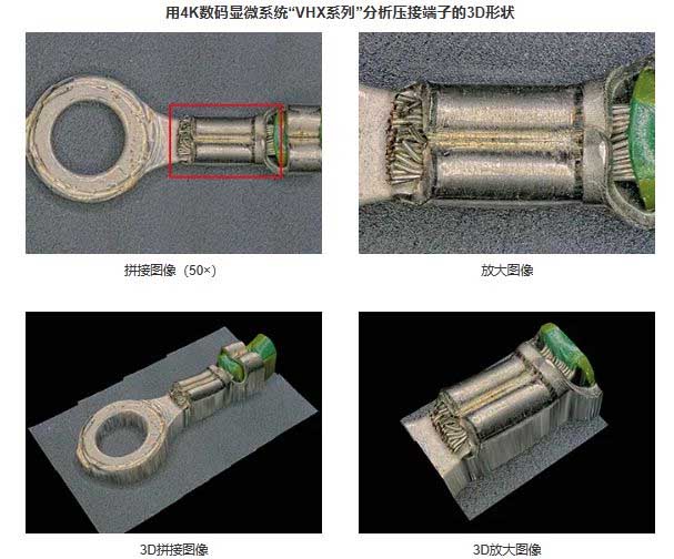
Observation og kvantitativ evaluering af ledningsnet og crimpterminaler – ledere og kerneledninger
2. Dimension parameter inspection
Crimp height: Adjust according to the terminal or mold manual, and the tolerance range must meet the requirements of the standard table.
Crimp width: The measurable crimp width (Cwm) should be controlled between 1Cw~1.1Cw, and the tolerance refers to the manufacturer’s specifications. Support angle: Den maksimale vinkel på lederkrympningsvingens tangent i forhold til den lodrette linje er ≤30°.
Støttehøjde: Den indbyrdes støttehøjde af krympevingerne er ≥1/4 af materialetykkelsen og ≥0,1 mm.
Afisoleringslængde: Beregnet efter formlen (L=0,5~1,0+A+B/2), sørg for, at der ikke er nogen brækket ledning eller formskade for enden af ledningen.
Krympe- og krympekvalitetsinspektion af ledningsnetterminaler til biler
Nøgle inspektionspunkter:
Terminalintegritet:
Se efter tegn på skade, bøjning, eller deformation af selve terminalen, indikerer et potentielt problem under crimpning.
Isolering Crimp:
Sørg for, at isoleringen er viklet ordentligt rundt om terminalen, uden gennemboring af ledningen eller isoleringen.
Trådstrengsplacering:
Verify that the wire strands are fully seated within the terminal barrel, with no protruding strands beyond the crimp area.
Bell Mouth:
The bell mouth (the flared edge of the terminal barrel) should be visible and properly formed, ensuring a good connection.
Crimp Height:
The height of the crimp should be within the specified range for the terminal and wire size, indicating proper compression.
Methods for Inspection:
Visuel inspektion:
A magnifying glass or microscope can be used to closely examine the crimp for any defects.
Pull Force Test:
Apply a controlled pull force to the crimped wire and measure the resistance to determine the crimp’s strength.
Cross-Section Analysis:
Cutting through a crimped terminal and examining the cross-section can reveal internal defects or improper crimping.
Bending Test:
Bøj ledningen flere gange for at vurdere stabiliteten af isoleringskrympen.
Elektrisk afprøvning:
Brug en kontinuitetstester til at kontrollere for elektriske afbrydelser eller kortslutninger.
Standarder og retningslinjer:
Industristandarder som IPC og WHMA giver retningslinjer for crimpkvalitet, herunder krav til trækkraft og krympehøjdespecifikationer.
Specifikke krympeværktøjer og -teknikker bør anvendes for at sikre ensartet og pålidelig krympekvalitet.
Regelmæssig kalibrering af crimpværktøjer er afgørende for at opretholde nøjagtig og pålidelig crimpning.
III. Mekanisk ydelsestest Trækkraftstest: Bekræft krympestyrken gennem en standard træktest for at sikre, at terminalen er fast forbundet til selen.
Krympende vingesymmetri: Krympevingen må ikke være helt symmetrisk, men endeafstanden skal være ≤1 gange materialetykkelsen.
Iv. Elektrisk ydeevne test Modstandstest: Mål modstanden ved krympepunktet for at sikre, at den elektriske forbindelse er lavimpedans og stabil.
Spændingsfaldstest: Kombineret med profilanalyse, kontrollere, om ledningsevnen af krympepunktet opfylder kravene.
5. Verifikation af miljøtilpasningsevne
Miljøresistenstest: simulere høj temperatur, ætsende eller fugtigt miljø for at vurdere vandtætheden, varmebestandighed og korrosionsbestandighed af krympepunktet.
6. Andre forholdsregler
Tool matching: use the crimping die that matches the terminal model to avoid poor crimping due to improper tools.
Staff operation specifications: strengthen the training of new employees to reduce the crimping position deviation or distortion caused by unskilled technology.
Electrical performance of automotive wiring harnesses and crimp terminals
Through the above systematic inspection, the reliability of terminal crimping and product life can be effectively guaranteed, and the system risk caused by connection failure can be reduced.
This article mainly introduces the technical requirements, diagrams and test methods for terminal crimping quality, as well as graphic and text standards. It is recommended to bookmark the YAXUN wiring harness engineer website.
Conductor Crimping of Wire Harness Terminals:
Terminal crimping bell mouth: There are bell mouths at both ends of the conductor crimping area or near the end of the insulation. The length is between 0.1mm~1/5 the length of the crimping area.
Wire core fixation: All wire cores (konduktører) are stored in the conductor crimping area. The wire core breakage meets the following criteria: no breakage for ≤20 cores, less than 5% for >20 kerner, and no cores flying out.
The front core of the wire harness is exposed: the end of the wire core can be seen at the front of the conductor crimping area. The exposed length of the front core is between 0.5~1.5mm and does not affect the terminal fit.
Note: Not available with flag terminals.
Conductor crimping: The conductor crimping area is neatly crimped, og der er ingen problemer såsom kerneeksponering eller skader i mellemsømmen. Krølleklo fejljustering ≤0,3 min.
Isoleringskrympning af ledningsnetklemmer
Isoleringshudlængde: Isoleringshuden og trådkernen kan ses mellem isoleringskrympeområdet og lederkrympeområdet, og isoleringshudens længde er >1/3c~≤1C. Note: Hvis isolationslængden = 1C og den er i kontakt med lederens krympeområde, trådkernen kan observeres ved at skubbe enden af isoleringen tilbage.
Isoleringskrympning: Isoleringskrympeområdet og isoleringshuden passer godt sammen, uden deformation, og krøllekloens forskydning er ≤0,3 mm.
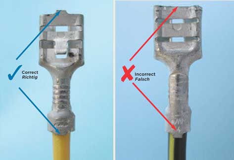
Krympningskvalitetsinspektionen af tilslutningskabelterminalen
Terminal deformation:
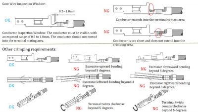
Terminalen er bøjet opad og nedad: the terminal mating area and the crimping area are straight, and the bending angle is ≤3°.
The terminal is bent left and right: the terminal mating area is aligned with the central axis of the crimping area, and the deviation angle is ≤5°.
Twist: The center seam of the insulation crimp is aligned with the axis of the conductor crimp, and the degree of twist should be ≤5°.
For the insulation bending fixed terminal, at a distance of 50mm from the conductor crimping area, perform an insulation bending test for five cycles (bending 45° → bending 90° in the opposite direction → reset, as one cycle) according to Figure 3. No pulling force is exerted on the lead during the test. After the test, the insulation crimping was good and the insulation skin did not come out from the insulation crimping area.
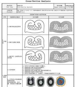
(2) Insulation crimping section
(3) Measurement method of crimping height and width: crimping width is measured with a caliper (accuracy: 1/100); crimping height is measured with a crimping height micrometer (accuracy: 1/1000), som vist på figur 5.
(4) Profile analysis method
• Use special cutting equipment to cut the conductor crimping area and insulation crimping area respectively according to Figure 6. When cutting, cut vertically and longitudinally in the middle of the crimping area, and avoid the grooves (reinforcing ribs) in the conductor crimping area.
• The cut section should be flat and without deformation, and the curl should not be opened.
• After cutting, polish the section to remove burrs. When polishing, pas på ikke at beskadige sektionen (såsom curling, revner, etc.).
• Den polerede sektion er belagt med ferrichloridopløsning (tilfreds: 35%-45%) for tydeligt at vise omridset af trådkernen og terminalvæggen.
• Brug et elektronmikroskop og kalibreret profilanalysesoftware til at analysere og måle profilens relevante parametre.
Note: Hvis terminalen er svær at fikse eller skære, og problemer såsom tværsnitsdeformation eller krølning opstår under polering, terminalen kan størknes i harpiks før polering.
(2) Træktestmetode
• Ifølge testmetoden i figur 7, slip isoleringskrympningen, fjern isoleringen ca. 200 mm fra lederens krympeområde, og omvendt svejs lederenden til lederen for at danne en strækring.
• After fixing the terminal with a special clamp and keeping the lead and conductor crimping area in a straight state, conduct a tensile test on the tension ring.
• Explosive force should not be used during the test. The test can be carried out by a tensile testing machine, and the moving speed of the machine head is between 25-50mm/min. During the test, observe and record the maximum tensile force value of the conductor, which should comply with the regulations of its wire diameter.
• Double-wire compression should be tested on each conductor one by one.