 English
 العربية
 bosanski jezik
 Български
 Català
 粤语
粤语 中文(漢字)
 Hrvatski
 Čeština
 Dansk
Dansk Nederlands
 Eesti keel
 Suomi
Suomi Français
 Deutsch
 Ελληνικά
 עברית
עברית Magyar
 Italiano
 日本語
日本語 한국어
한국어 Latviešu valoda
 Bahasa Melayu
 Norsk
Norsk پارسی
پارسی Polski
 Português
 Română
 Русский
 Cрпски језик
 Slovenčina
 Slovenščina
 Español
 Svenska
 தமிழ்
தமிழ் ภาษาไทย
 Tiếng Việt
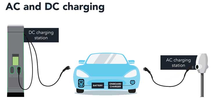
Elbiler bruker både rask og langsom lading, med hurtiglading ved bruk av høyeffekts DC-ladere for rask etterfylling, mens langsom lading bruker AC-ladere lenger, mer gradvis lading hjemme eller på jobb.
Rask lading:
Fart:
Tilbyr betydelig raskere ladetider sammenlignet med langsom lading, slik at elbiler kan gjenvinne en betydelig del av rekkevidden på kort tid.
Makt:
Bruker høyeffekts DC-ladere, vanligvis leverer 50 kW eller mer, til og med overskrider 350 kW.
Infrastruktur:
Krever spesialisert utstyr og infrastruktur, gjør den mer egnet for offentlige ladestasjoner og kommersielle applikasjoner.
Vanlige applikasjoner:
Ideell for langdistansereiser og situasjoner der rask påfylling er nødvendig.
Batteripåvirkning:
Mens hurtiglading kan være praktisk, hyppig bruk kan potensielt degradere batteriet raskere på grunn av høy strømtilførsel og varme som genereres.
Ladetid:
Kan lade batteriet opp til 80% kapasitet på så lite som 30 minutter, men lader fra 80% til 100% kan ta lengre tid på grunn av redusert ladehastighet for batterisikkerhet.
Sakte lading:
Fart: Karakterisert av lengre ladetider, krever ofte timer for å fullade en elbil.
Makt: Bruker AC-ladere med lavere effekt, vanligvis fra 3 kW til 22 kW.
Infrastruktur: Mer tilgjengelig, spesielt for hjemmebruk, og rimeligere og enklere å installere.
Vanlige applikasjoner: Ideell for over natten eller lengre ladeøkter hjemme, arbeid, eller andre steder hvor kjøretøyet er parkert i en lengre periode.
Batteripåvirkning: Generelt skånsommere mot batteriet og kan bidra til å forlenge levetiden.
Ladetid: Det kan ta flere timer å nå full lading.
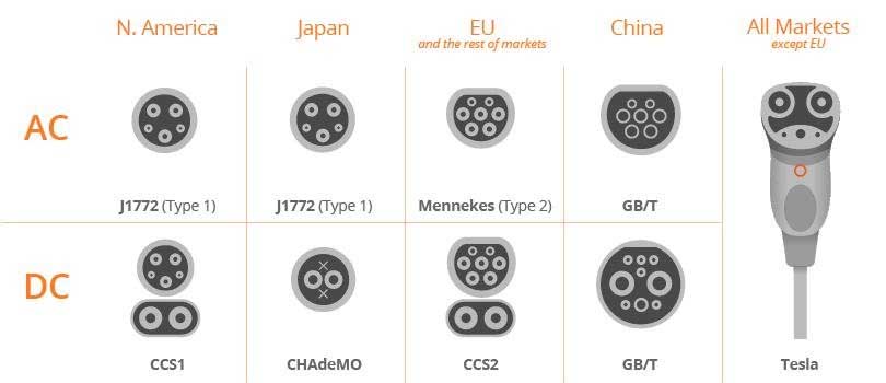
N. Amerika, Japan, EU, Kina og resten av markedene Typer elektriske kjøretøyladere
For nye energikjøretøyer drevet av batterier, lading er en viktig del. Selv om det kan være batteribyttetjenester som ligner på tanking i fremtiden, det er konservativt anslått at innenfor 10 år, ulike raske og langsomme ladninger må stole på for å fylle opp batteriene. Denne gangen vil jeg kort introdusere deg ladesystemet til nye energikjøretøyer.
Ladesystemet kan deles inn i to metoder: vanlig lading og hurtiglading. Ut fra utseende og størrelse å dømme, forskjellen mellom ladeportene er faktisk veldig enkel. Hurtigladeporten er stor og har 9 hull, og den langsom ladeporten er liten og har 7 hull. På denne måten, selv nybegynnere vil ikke gjøre feil. Generelt, to ladeporter vil bli utformet foran og bak på bilen. Noen modeller vil også designe to ladeporter sammen, for eksempel foran eller bak på bilen. Bileiere kan velge lademetode i henhold til deres ladetidsbehov.
Rask ladegrensesnitt (hurtiglading)
Hurtiglading er en DC-lademetode. Ladestrømmen må være større, som krever bygging av hurtigladestasjoner. Det krever ikke at strømbatteriet er fulladet, men dekker kun behovene ved fortsatt kjøring. I denne lademodusen, bare 50% til 80% av strømbatteriet kan lades inn 20 til 30 minutter. Grunnen ladehaug (utstyr) sender direkte ut likestrøm for å lade kjøretøyets batteri. Det elektriske kjøretøyet trenger bare å tilby lading og relaterte kommunikasjonsgrensesnitt.
Fordelene med hurtiglading: kort ladetid, rask flyt av ladede kjøretøy, og lagring av parkeringsplass ved ladestasjonen.
Ulemper med hurtiglading: lavere ladeeffektivitet, høyere laderproduksjon, installasjons- og driftskostnader. Ladestrømmen er stor og krever høy ladeteknologi og -metoder, som har en negativ innvirkning på levetiden til strømbatteriet. Det er lett å forårsake unormaliteter i strømbatteriet og utgjøre en sikkerhetsrisiko. Dessuten, høystrømslading vil ha innvirkning på det offentlige strømnettet og påvirke strømforsyningskvaliteten og sikkerheten til strømnettet.
Regelmessig lading (langsom lading)
Denne lademodusen er AC-lading. Det eksterne strømnettet gir 220V sivil enfaset vekselstrøm til elbilens innebygde lader, og den innebygde laderen lader strømbatteriet. Det tar vanligvis 5 til 8 timer for å fullade.
Fordelene med vanlig lading: ladehaugen (ladeboks) er lav i pris og enkel å installere. Strømnettets lave dalstrøm om natten kan brukes til lading for å redusere ladekostnadene. I løpet av ladeperioden, ladestrømmen er liten og spenningen er relativt stabil, som kan sikre sikkerheten til strømbatteripakken og forlenge levetiden til strømbatteriet.
Ulemper med vanlig lading: Ladetiden er for lang og det er vanskelig å møte behovene til nøddrift av kjøretøyet.
Rask ladegrensesnitt
DC+: DC effekt positiv
DC -: DC strømforsyning negativ
PE: Bakke (bakke)
S+: Kommunikasjon CAN-H
S-: Kommunikasjon CAN-L
CC1: Bekreftelse av ladetilkobling
CC2: Bekreftelse av ladetilkobling
A+: 12V+
EN-: 12V-
forskjellen mellom AC og DC for EV-lading
Hvordan bekrefter du om CC1 og CC2 er riktig tilkoblet?
The following is the CC1 charging pile connection detection schematic diagram.
As you can see from the chart below, to determine whether the connection is normal, you can confirm it by the voltage at the detection point. Different voltages are obtained by dividing voltage by different resistors.
Then there is the CC2 vehicle control device connection confirmation schematic diagram.
After it is turned on, the two resistors divide the voltage to obtain a voltage of 6V, otherwise a voltage of 12V is obtained.
Taking the BYD e6 as an example, the vehicle body connection device is used to conduct and input external electrical energy to the power battery when the vehicle is charging. The charging port cover has damping characteristics, det er, check whether the resistance between “CC1” and “PE” on the charging port is 1KΩ; at the same time, you need to check whether the connection between the charging port and the power manager is normal.
Slow charging interface
CC: Vehicle control device connection confirmation
CP: Charging pile connection confirmation
PE: Bakke (bakke)
L: Three-phase alternating current “U”
N: Three-phase AC “neutral”
NC1: Three-phase alternating current “V”
NC2: Three-phase alternating current “W”
Normally NC1 and NC2 are empty.
L and N are the two wires connected to our household 220V.
How do CC and CP confirm whether the connection is normal?
The “cable control box” and the “vehicle control device” mutually confirm whether the connection is correct.
Først, the “cable control box” will pass CP detection point 1 and detection point 4 to detect whether the voltage is 12V. If it is not connected properly, there will be no ground at detection point 4, and the voltage will not be detected. If the connection is good, detection point 4 is connected to the vehicle ground through PE, and the voltage is 12V at this time. After there is 12V power, the “cable control box” will connect S1 to PWM, otherwise S1 will be connected to +12.
Then, the vehicle control device will detect the R3 resistance through CC to confirm whether the charging gun is connected to the vehicle socket. If not, the resistance will be infinite, otherwise there will be a corresponding resistance value.
Here, the vehicle control device will set the power of the on-board charger (usually set by the manufacturer by default):
The on-board charging device determines the maximum charging current of the control box on the cable through the duty cycle signal of CP. The general setting ratio is as follows:
Samtidig, the on-board charging device will also determine the rated capacity of the cable through the RC on the CC.
Endelig, after calculating the rated capacity of the charging cable and the current of the control box on the cable, the vehicle control device sets the maximum power of the on-board charger to their minimum value.
Having said so much, some people must ask: “Why are there two charging interfaces? Isn’t it good to unify them into one?” This is mainly determined by fast charging.
You must know that the charging process of a vehicle is not just from the power grid to the battery, but also requires passing through charging piles, charging cables, charging plugs, and vehicle socket interfaces before entering the vehicle. From the previous principles, we also know that for AC charging, after entering the vehicle, it does not go directly to the battery, but also passes through the two levels of on-board charger and BMS.
For fast charging, compared with AC charging, the charging power is not limited to the specific charging voltage and current, ranging from 20kW, 40kW, 60kW to 200kW, 250kW, and 350kW. As long as the input (grid) and output (vehicle) support it, it can be done very well.
The power from the grid first enters the charging pile and then reaches the vehicle through the charging cable. Most charging cables are fixed on the charging pile, and the other end is a gun-shaped plug connected to the vehicle (this connection method is called connection method C in the standard).
There are also a small number of charging piles that are isolated and require an independent cable, with both ends connected to the charging pile and the vehicle (connection method B). As for the way the charging cable is fixed on the vehicle (connection method A), it has almost no application. AC charging can use connection mode B and connection mode C. For AC charging current greater than 32A and DC charging, only connection method C can be used.
Since the vehicle’s power system is a DC system, when charging with AC, AC power cannot directly charge the battery. It needs to go through a component called an on-board charger (OBC, On-board Charger) to convert AC to DC and transform the voltage according to the command of BMS before supplying it to the battery.
In this car charger composition diagram, there are two core components-ACDC rectifier and DCDC transformer (power unit in the picture). The former is used to convert alternating current into direct current that is acceptable to the vehicle battery, and the latter is used to adjust the voltage of the direct current.
According to the BMS command, the charging current and voltage are dynamically adjusted to adapt to the charging needs of the battery at different stages. For eksempel, during constant current charging, as the battery power increases, the charging voltage also needs to increase. It is also responsible for converting low voltage and charging the 12V small battery.
During DC charging, the DC pile itself is an ACDC rectifier plus a DCDC transformer, which directly converts AC power outside the vehicle according to the needs of the BMS, replacing the role of the on-board charger. Derfor, DC charging piles are also called off-board chargers.
