 English
 العربية
 bosanski jezik
 Български
 Català
 粤语
粤语 中文(漢字)
 Hrvatski
 Čeština
 Dansk
Dansk Nederlands
 Eesti keel
 Suomi
Suomi Français
 Deutsch
 Ελληνικά
 עברית
עברית Magyar
 Italiano
 日本語
日本語 한국어
한국어 Latviešu valoda
 Bahasa Melayu
 Norsk
Norsk پارسی
پارسی Polski
 Português
 Română
 Русский
 Cрпски језик
 Slovenčina
 Slovenščina
 Español
 Svenska
 தமிழ்
தமிழ் ภาษาไทย
 Tiếng Việt

Projetar pontos de crimpagem para conectar chicotes de arame envolve a seleção de terminais de crimpagem apropriados e garantir técnicas de crimpagem adequadas para criar conexões confiáveis e seguras. Este processo inclui a escolha do tipo de terminal certo para o medidor de arame específico e a aplicação, Usando uma ferramenta de crimpagem adequada, e verificar a qualidade do crimp para evitar problemas como shorts ou conexões fracas.
Pontos de crimpagem de design para conectar chicotes de arame
1. Seleção de Terminais:
Calibre do fio:
O tamanho do fio (American Wire Gauge ou AWG) determina o tamanho e tipo do terminal de crimpagem.
Tipo de terminal:
Os tipos de terminais comuns incluem terminais em anel, terminais de espada, e conectores de bunda. Terminais de anel são fixados em parafusos ou pinos, terminais em forma de espada têm formato de garfo, e conectores de topo unem dois fios.
Material e Acabamento:
Considere materiais como cobre ou latão e acabamentos como estanho para resistência à corrosão e baixa resistência.
Isolamento:
Terminais podem ter isolamento, fornecendo proteção e facilidade de conexão.
2. Processo de crimpagem:
Prepare o fio:
Descasque o isolamento da extremidade do fio até o comprimento adequado, garantindo que nenhum fio seja quebrado.
Selecione uma ferramenta de crimpagem:
Escolha uma ferramenta apropriada para o tipo de terminal e bitola do fio.
Posicione a crimpagem:
Insira o fio e o terminal na ferramenta de crimpagem, garantindo o posicionamento correto.
Crimpagem:
Aplique força suficiente para criar uma crimpagem segura, seguindo as instruções da ferramenta.
Verificação:
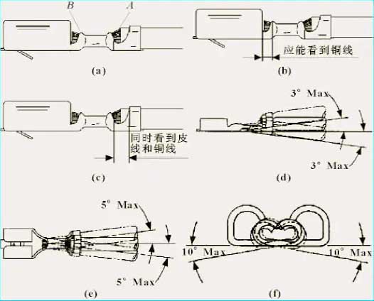
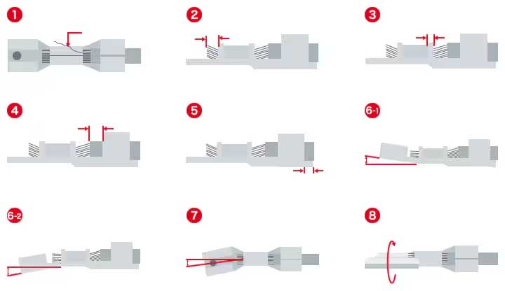
Verifique a qualidade da crimpagem medindo a altura da crimpagem, verificando a penetração adequada do isolamento, e verificando a durabilidade da conexão.
3. Controle de qualidade:
Altura de crimpagem: É necessária uma altura específica para penetração adequada do isolamento e aderência do fio.
Penetração de Fio: Certifique-se de que o cilindro do terminal penetre totalmente nos fios do fio.
Teste de vibração: Sujeite as conexões crimpadas à vibração para verificar se há afrouxamento ou quebra.
Resistência à tracção: Verifique a resistência da conexão crimpada às forças de tração.
4. Considerações de projeto:
Tipo de conector: Selecione conectores que acomodem a bitola do fio e o tipo de terminal.
Densidade e tamanho do circuito: Considere o número de fios e o tamanho geral do conector.
Fatores Ambientais: Considere fatores como temperatura, umidade, e vibração.
Padrões e Certificações: Garanta a conformidade com os padrões relevantes do setor.
5. Crimpagem Automatizada:
Máquinas Automatizadas:
Utilize máquinas para tarefas repetitivas de crimpagem para garantir consistência e eficiência.
Benefícios de automação:
Reduza erros manuais, aumentar a velocidade de produção, e manter uma qualidade de crimpagem consistente.
Ponto de crimpagem do chicote de conexão, também chamado de ponto perfurante, ponto de contato, ponto de emenda. O design do ponto de crimpagem tem um grande impacto na estabilidade das funções elétricas do veículo e no custo do chicote elétrico. Este artigo discute o design de pontos de crimpagem.
Definição de ponto de crimpagem:
O ponto de crimpagem do chicote de fios refere-se ao ponto de conexão onde mais de 2 os fios do chicote são articulados.
Como mostrado na figura abaixo, este ponto de friso (SP) consiste em fio 1, Arame 2, e fio 3. O 3 os fios estão conectados entre si dentro do chicote. O ponto de conexão articulado dos três fios dentro do chicote é o ponto de crimpagem, também chamado de ponto de emenda, e o ponto de perfuração do arnês.
Tipo de ponto de crimpagem
Pontos de emenda do chicote elétrico automotivo, métodos comumente usados incluem soldagem ultrassônica, Crimpagem de terminal em forma de U, etc..
Soldagem ultrassônica
O princípio da soldagem ultrassônica de metal é usar energia vibratória em frequência ultrassônica (20-40kHz) para transmitir ondas de vibração às superfícies de dois objetos metálicos que precisam ser soldados. Sob pressão estática, as duas superfícies metálicas são friccionadas uma contra a outra, formando assim uma fusão entre as camadas moleculares.
Como mostrado na figura acima, o 50/60 A corrente Hz é convertida em 15, 20, 30 ou 40 Energia elétrica KHz por um gerador ultrassônico. A energia elétrica de alta frequência convertida é convertida novamente em movimento mecânico da mesma frequência através do transdutor, e então o movimento mecânico é transmitido à cabeça de soldagem através de um conjunto de dispositivos de buzina que podem alterar a amplitude. A cabeça de soldagem transmite a energia vibratória recebida para a junta da peça a ser soldada. Nesta área, a energia de vibração é convertida em energia térmica através do atrito, derretendo o metal.
A soldagem ultrassônica pode ser usada para unir materiais idênticos e materiais diferentes, como cobre e alumínio. Porque os metais são soldados diretamente entre si, sem materiais adicionais, como ponteiras, solda, ou fluxo são necessários. Além disso, soldagem ultrassônica produz baixo estresse térmico nas peças (a temperatura de soldagem é muito inferior ao ponto de fusão das peças), portanto, as propriedades do próprio material soldado e as propriedades dos materiais circundantes não mudam. Se a manga de isolamento permanecer intacta.
Como soldar & Crimpagem de fios automotivos
Padrões de soldagem ultrassônica
O padrão de soldagem mais confiável SAE/USCAR-38 emitido em conjunto pela Sociedade Americana de Engenheiros Automotivos e pelo Comitê de Pesquisa Automóvel dos Estados Unidos. Uma definição abrangente do processo de soldagem ultrassônica entre cabos e terminais automotivos fornece uma referência importante para especificações da indústria.
Vantagens e desvantagens da soldagem ultrassônica:
As vantagens deste método são velocidade rápida, economia de energia, alta resistência à fusão, boa condutividade, sem faíscas, perto do processamento a frio, alta eficiência, boa condutividade, proteção ambiental e segurança. É a tendência de desenvolvimento de contatos de chicote de fios.
As desvantagens são que as peças metálicas a serem soldadas não podem ser muito espessas (geralmente menor ou igual a 5mm), as juntas de solda não podem ser muito grandes, e pressão é necessária. Os preços dos equipamentos de soldagem e os custos de manutenção são relativamente altos.
Crimpagem de terminal em forma de U
A crimpagem é um processo que aplica pressão à área de contato entre fios e terminais para formar uma conexão firme. Durante o processo de crimpagem, o condutor é comprimido pela manga e deforma-se nas direções de longitude e latitude, formando uma solda fria. A película de óxido original na superfície do condutor e da luva está deformada e rompida, o condutor e a superfície de metal puro da luva terminal estão em contato total e próximo, e micromovimentos ocorrem durante o processo de extrusão e deformação.
A crimpagem física e uniforme dos fios de cobre através de terminais em forma de U é um método de contato comumente usado atualmente. O diagrama de crimpagem do terminal em forma de U é mostrado na figura abaixo.
Figura Diagrama de crimpagem de terminal em forma de U
Padrão de crimpagem de terminal em forma de U
O padrão USCAR é um padrão de conector especializado, e USCAR 21 é uma especificação de desempenho de crimpagem de terminal. É fornecida uma definição abrangente do processo de crimpagem do terminal do chicote elétrico automotivo, fornecendo uma referência importante para especificações da indústria.
Vantagens e desvantagens de crimpagem de terminal em forma de U:
As vantagens deste método são a fácil operação, alta eficiência, boa condutividade, e equipamentos de crimpagem e terminais em forma de U mais baratos;
A desvantagem é que, em comparação com a soldagem ultrassônica, requer o uso de materiais de crimpagem e aumenta o peso.
Seleção da localização do ponto de crimpagem:
A localização do ponto de crimpagem não está relacionada apenas ao custo do chicote de fios, mas também à qualidade do chicote de fios. O projeto de emenda irracional não só aumentará o custo do chicote elétrico, mas também aumentar o peso do chicote elétrico, e também pode causar dificuldades de montagem e outros problemas.
Escolha um local onde o chicote elétrico seja relativamente estável. Não escolha peças móveis ou locais com maior interferência.
Organize o ponto de crimpagem próximo à interseção de cada linha de sinal e o tronco, o que pode efetivamente reduzir fios e economizar custos.
3. Seleção de locais de contato para evitar chicotes de loopback. Principalmente na área molhada, existem chicotes de retorno, o que não é propício à vedação do ponto de emenda.
Evite pressão comum de mais de 10 fios no mesmo ponto de crimpagem. Mais uma vez do que 10 os fios são pressionados juntos, pontos de crimpagem adicionais precisam ser definidos.
Para o mesmo ponto de crimpagem, o diâmetro do diâmetro mínimo do fio não pode ser inferior a 10% da soma dos diâmetros dos fios de todos os fios no ponto de crimpagem.
6. A soma dos diâmetros dos fios nos lados esquerdo e direito do ponto de crimpagem deve ser tão igual quanto possível, e o menor não deve ser menor que 50% do outro lado.
7. O diâmetro do fio mínimo no ponto de crimpagem deve ser tão grande quanto 16% do diâmetro máximo do fio no ponto de crimpagem.
8. Quando um fio conecta dois pontos de crimpagem, a distância entre os dois pontos de crimpagem não deve ser inferior a 150 mm. Na foto abaixo, a distância entre SP1 e SP2 é maior que 150 mm.
A distância entre o ponto de crimpagem e o ponto de ramificação, fivela/gravata precisa ser maior que 50 mm, e a distância entre os contatos também deve ser superior a 50mm (exceto a linha de lata), de modo a evitar efetivamente o contato entre contatos.
Proteção de ponto de crimpagem
Se a proteção dos contatos do chicote elétrico não for razoável, o isolamento nos contatos do chicote de fios pode ser perfurado, ou água pode entrar nos contatos, causando uma falha de curto-circuito.
De um modo geral, a distribuição de contatos automotivos é dividida em duas categorias: área seca e área molhada. Os contatos na área seca precisam ser protegidos com fita especial; os contatos na área úmida precisam ser protegidos com tubo termorretrátil contendo cola ou cola butílica para obter um efeito de vedação à prova d'água.
Como mostrado na figura acima, a área abaixo da linha de vadear é chamada de área úmida, e o restante fora da área de desumidificação é a área seca.
Resumir:
Este artigo introduz sistematicamente a definição, classificação, seleção de localização e proteção de pontos de crimpagem. Ao fazer design de layout e design de princípio, você precisa prestar atenção aos pontos de crimpagem. Se você deseja melhorar rapidamente as capacidades de design de chicotes elétricos automotivos, preste atenção aos cursos de chicotes elétricos dos engenheiros de chicotes elétricos YAXUN.