 English
 العربية
 bosanski jezik
 Български
 Català
 粤语
粤语 中文(漢字)
 Hrvatski
 Čeština
 Dansk
Dansk Nederlands
 Eesti keel
 Suomi
Suomi Français
 Deutsch
 Ελληνικά
 עברית
עברית Magyar
 Italiano
 日本語
日本語 한국어
한국어 Latviešu valoda
 Bahasa Melayu
 Norsk
Norsk پارسی
پارسی Polski
 Português
 Română
 Русский
 Cрпски језик
 Slovenčina
 Slovenščina
 Español
 Svenska
 தமிழ்
தமிழ் ภาษาไทย
 Tiếng Việt

Utformingen av Automotive Circuit Harnesses trenger å vurdere sikkerhet omfattende, Pålitelighet, Elektromagnetisk kompatibilitet og vedlikeholdskonferanse. Følgende er kjernedesignmetodene og prinsippene:
1. Designprinsipper og spesifikasjoner
Sikkerhet først
Høyspentledninger (som nye energikjøretøyer) må ta i bruk en tosporsdesign for å unngå kroppen som et jordingspunkt, og følg strengt kravene til høyspenningsmotstand og beskyttelsesnivå.
Selene må unngå kollisjonsdeformasjonsområder (som anti-kollisjonsbjelker og innvendige dører) for å forhindre isolasjonsskader og lekkasje.
Ledningene må pakkes pent sammen, festet og klemt, og beskyttet når du passerer gjennom hull, og forskyvningen under nødbremsing bør reserveres.
Modulært og segmentert design
Del selemodulene (som motorsele, instrument sele, dørsele, etc.) i henhold til funksjonsområder for å redusere lengden på hovedselen, redusere kostnader og lette demontering og montering.
Segmenterte koblinger bør plasseres på et skjult og lett å vedlikeholde sted for å unngå risiko for støt.
Elektromagnetisk kompatibilitet (EMC)
Høyspentledninger bør føres under chassiset så mye som mulig for å redusere elektromagnetisk interferens. For sensitive signallinjer (som CAN-buss), tvunnet par eller skjermet ledningsdesign brukes for å forbedre anti-interferensevnen.
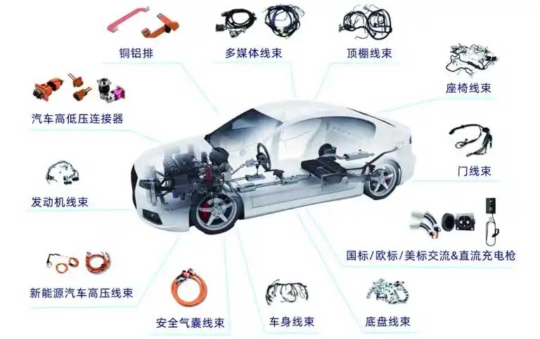
Detaljert forklaring av bilkretsdiagramgjenkjenning og analyse
2. Arrangementsmetode
Fiksering og avstandskrav
Avstanden mellom tilstøtende festepunkter til høyspentledninger bestemmes i henhold til tverrsnittsarealet:
Når tverrsnittsarealet er større enn 16 mm², avstanden er ≤300 mm;
Når tverrsnittsarealet er ≤16 mm², avstanden er ≤200 mm.
Avstanden mellom selen og de stasjonære delene er ≥10 mm, avoiding contact with sharp edges, høye temperaturer, og bevegelige deler. Om nødvendig, add a heat shield or corrugated tube for protection.
Wiring path optimization
High-voltage harnesses should avoid crossing or winding, and the positive and negative wires should be routed in the same path. De tilhørende selene (such as the three-phase wires of the motor) should be arranged symmetrically.
When the cockpit and the front cabin harnesses are connected, they must be passed through the body sheet metal holes and sealed to prevent water and dust leakage.
Three-dimensional layout specifications
Combine the body sheet metal structure to plan the direction of the wiring harness to ensure the convenience of assembly and maintenance. Kontakten er anordnet i en posisjon som er lett å betjene for å unngå vanskeligheten med å koble til og fra med én hånd8.
Iii. Spesialdesign av høyspent ledningsnett
Dobbeltsporssystem og koblingsvalg
Høyspentkretsen vedtar strengt en tosporsdesign. Koblingen må ha sløyfeforrigling, høyt beskyttelsesnivå (som IP67) og skjermingsfunksjon, og modne leverandører foretrekkes.
Høyspent ledningsnett som drivsystemer og ladestasjoner må arrangeres uavhengig og jevnt symmetrisk.
Protective tiltak
Motorrommets ledningsnett må være motstandsdyktig mot høy temperatur og vibrasjoner, og faste punkter må settes hver 200 mm, med en avstand på ≥100 mm fra varmekilden.
Use plastic protective covers when passing the door wiring harness through holes, and arrange them on the dry side of the door to reduce the risk of water leakage.
IV. Verifisering og optimalisering
Gjennomgang av ordningen
The design stage needs to pass multi-departmental reviews (design, behandle, kvalitet, produksjon) for å sikre gjennomførbarheten av ordningen.
Prøveproduksjon og testing
Verify the two-dimensional drawings through three-dimensional wiring diagrams and schematics, og opptre funksjonell, durability and environmental adaptability tests after trial production.
The above design methods need to be comprehensively optimized in combination with the vehicle electrical load, driftsforhold (such as continuous/short-time/random working system) og miljøfaktorer (temperatur, vibrasjon).
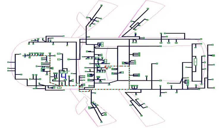
Forskning og anvendelse av designmetode for ledningsnett for biler
Som en viktig andel av ledningsnettkostnaden, ledningsnettet i bilen har en betydelig innvirkning på optimaliseringen av kostnadene for ledningsnettet. Det er også direkte relatert til sikkerheten og påliteligheten til kjøretøyets elektriske apparater. Basert på arbeidspraksis, denne artikkelen oppsummerer mange betraktninger for sløyfedesign både når det gjelder kostnad og ytelse, og foreslår spesifikke kontrollstrategier og implementeringstilnærminger, gir teknisk støtte for effektiv og nøyaktig design av ledningssløyfe. Det har sterk veiledende betydning for ledningsnettdesignere.
1 Introduksjon
Ledningsprodukter fungerer som tilkoblingsbærer for elektriske funksjoner i biler og realiserer kretsforbindelsen mellom forskjellige elektriske komponenter. Startpunktet og sluttpunktet for hver kretsforbindelse utgjør sløyfen i ledningsnettproduktet. Det kan sies at ledningsnettkretsen er kjernen i ledningsnettproduktet. Kvaliteten på kretsdesignet til ledningsnettproduktet bestemmer direkte sikkerheten og påliteligheten til kjøretøyets ledningsnett. Ettersom graden av elektrifisering av kjøretøy øker, dataene til elektriske komponenter øker, signalsamspillet mellom elektriske apparater blir mer og mer intimt, og antallet ledningsnettsløyfer for biler øker også kraftig. Dataene for ledningsnettet for generelle kjøretøymodeller har nådd nesten 1,000 (Figur 1).
Hvordan man kan optimalisere og koordinere et så stort antall kretser er et vanskelig problem som design av ledningsnett for biler står overfor.
Den eksisterende tekniske informasjonen om design av ledningsnett for biler gir hovedsakelig designveiledning for ledningsledningsdesign i valg av ledningsnettmaterialer og produksjons- og prosesskoblinger, men mangler systematisk analyse av planleggings- og designkonseptene til ledningsnettkretser. Denne artikkelen forklarer de relevante hovedpunktene for ledningssløyfedesign fra to aspekter: kostnad og ytelse, og gir spesifikke kontrollveier. Den har en viss veiledende rolle i utformingen av ledningsnettkretser.
2 Kostnadsbasert sløyfedesignmetode
Ledningsnettsløyfen står for ca 90% av ledningsnettets materialkostnad, inkludert ledninger og kontakter. For å kontrollere kostnadene ved design av ledningsnett, vi må starte fra optimaliseringen av ledningssløyfedesign.
Angående bruk av ledninger, hvordan man oppnår sløyfetilkoblingsfunksjonen med minimum ledningslengde er det første problemet som vurderes i sløyfedesign. Dette involverer to aspekter av designelementer: plassering av elektriske komponenter og valg av ledningsnettoppsett. Disse to faktorene er uavhengige, men henger sammen og har en betydelig innvirkning på bruken av trådlengden.
Først, det er nødvendig å bestemme koblingsmetoden til kretsen basert på prinsippet om komponenter, og bestemme deretter den foreløpige posisjonen til utformingen av hver komponent i kjøretøymiljøet. Valget av ledningsnettets layoutbane er basert på layoutposisjonen til komponentene, bruke den korteste ledningsnettlengden for å dekke så mye av komponentlayoutområdet som mulig. Dette er også prototypen til kjøretøyets elektriske topologi.
Etter å ha fullført kjøretøytopologikonstruksjonen, det må utformes og verifiseres. Ved å beregne den spesifikke ledningsbruken, vi kan avgjøre om layoutposisjonen til komponentene og ledningsnettets layoutbane er rimelige (det finnes for tiden et stort antall programvare på markedet som kan realisere denne funksjonen). Den spesifikke metoden er å sammenligne ved å justere delene en etter en. Som vist i figur 2 og figur 3, designene til forskjellige BCM-layoutposisjoner sammenlignes for å sjekke lengden og mengden ledninger som brukes i kjøretøyet, og deretter bestemme hvilken plassering av BCM-oppsettet som er bedre.
I denne prosessen, gjensidig påvirkning forekommer ofte: justeringen av utformingen av komponent A vil påvirke valget av plassering av komponent B. Derfor, etter å ha bestemt virkningen av hver komponent og ledningsnettbanen på lengden av ledningen en etter en, den som har større innvirkning på ledningens lengde vil bli valgt som den foretrukne løsningen i første omgang. På dette grunnlaget, topologien bygges om og andre sekundære løsninger sammenlignes og analyseres på nytt. Dette oppnår en topologidesignplattform med den minste ledningslengden.
En perfekt topologi kan sikre minimalt med ledningsbruk. Samtidig, om bruk av ledninger, det tradisjonelle designkonseptet har klare krav til valg av ledninger. For å unngå forvirring i terminalplugging, flere trådfarger brukes ofte for å skille dem. Imidlertid, ettersom produksjonsnivået og inspeksjonsmetodene fortsetter å forbedres, ledningsfargene på ledningene kan faktisk utformes og justeres riktig for å realisere sløyfefunksjonen med minimum antall ledningstyper, som også er en metode for å redusere sløyfedesignkostnaden fra et designperspektiv.
For kontakter, hvordan man kan minimere bruken av koblinger og redusere overføringssløyfer er det som må fokuseres på i sløyfedesign. Her, ingeniøren for ledningsnettet må forvandles til en systemdesigner, og designarbeidet med å redusere bruken av koblinger og overføringsløkker må flyttes til design og planlegging av elektriske komponenter. Det er to hovedaspekter å vurdere:
På den ene siden, funksjonelle kretser av elektriske komponenter kan skilles i henhold til kjøretøymodellkonfigurasjoner. For eksempel, for kollisjonsputekontrollere, grunnleggende funksjonskretser kan designes i samme kontakt, mens avanserte eller utvidede funksjoner kan ordnes i en annen kontakt. På denne måten, bare én kontakt kan brukes på lavprismodeller, og den elektriske kretsfunksjonen kan også realiseres.
På den annen side, det kan også planlegges i henhold til koblingsområdet til kretsen, som kollisjonsputekontrolleren. Noen designere vil vurdere å designe funksjonene til chassiset i samme kontakt og funksjonene til instrumentpanelet i en annen kontakt. Denne typen planlegging kan redusere gjensidig overføring av kretser i ulike regioner. Denne områdebaserte funksjonelle sløyfedesignen er spesielt effektiv for elektriske komponenter med et stort antall tilkoblede pinner (for eksempel BCM-kontrollere).
3 – Kretsdesignmetode basert på ledningsnettytelse
Ledningsnettsløyfen er kjernen i å realisere kretsforbindelsen. Sikkerheten og påliteligheten til kretsforbindelsene er krav som må oppfylles. Ledningene og kontaktene i kretsdesignet må være i samsvar med kravene til belastning og miljø. Dette innholdet er beskrevet i detalj i andre designmaterialer. Denne artikkelen forklarer bare hvordan du sikrer utformingen av loopytelse fra perspektivet til valg av loopbane.
Først, kretsdesignet må unngå uoppdagbare feilmoduser. Som vist i figur 4, den bakre delen av sikringen er koblet parallelt med reléspoleenden og kontaktenden. Denne typen design er veldig vanlig i kjøretøykretsdesign. Denne utformingen er åpenbart rimelig når reléspolens ende- og kontaktendeterminaler er forskjellige. Imidlertid, når reléspolens ende og kontaktende terminaler er de samme, nåværende elektrisk inspeksjonsutstyr kan ikke identifisere en slik feilmodus når terminalene er satt inn i reléhullene i feil posisjon.
Derfor, denne sløyfedesignmetoden kan ikke brukes i noen tilfeller. Selvfølgelig, ulike designingeniører står overfor ulike designmiljøer og produksjonsmiljøer, og de spesifikke feilmodusene vil også være forskjellige, men unngåelse av feilmoduser i kretsdesign er den første tingen å vurdere.
På den annen side, the current level of automotive electronics has improved significantly. As an electronic carrier, the electromagnetic environment faced by automobiles is also more complex, and how to reduce electromagnetic interference in wire harness circuit design is an inevitable topic. Wire coupling interference (Figur 5), power supply interference, ground interference, radiation interference, osv. will all have adverse effects on the normal operation of electrical devices. The circuits in the wire harness are bundled together, and the wire coupling interference generated between the wire harness loops and between the wire harness and the metal conductor is particularly prominent in the wire harness.
To reduce wire coupling interference in loop design, we must first distinguish between interference loops and sensitive loops. To put it simply, induktive belastningskretser som tennspoler, høyttalere, motorer, osv. er interferenskretser, mens kretser som bildebehandling, radarsonder, LED-lys med lav effekt, og ulike sensorer er følsomme kretser. Interferensløkker og sensitive løkker må arrangeres separat under designprosessen. Tester har vist at å øke avstanden mellom ledningene kan redusere høyfrekvent interferens (Figur 6). Hvis skillet ikke kan gjøres, funksjonell testing må utføres ved å injisere interferens i ledningene for å bestemme riktigheten av kretsdesignet.
Samtidig, for å redusere påvirkningen av ledningsnettstråling og kobling, kretssløyfeområdet og ledningsnettets lengde bør reduseres så mye som mulig. I utformingen av hele kjøretøyet, det er nødvendig å minimere løkkeområdet til ledningsnettet, spesielt kraftledningene og jordledningene. Det kreves at ledningsnettene i sløyfen skal føres parallelt så mye som mulig og festes så nært metalllegemet som mulig for å redusere sløyfearealet, og avstanden mellom ledningene bør ikke overstige 50 cm.
I tillegg til vurderingen av utformingen av interferensløkker og sensitive løkker, antiinterferenskomponentene tvunnet par og skjermede ledninger som brukes på ledningsnettet, må også tas hensyn til i sløyfedesignen for å oppnå skjermingsforventninger. De to ledningene til det tvunnede paret skal ha samme diameter og lengde, og vridningsavstanden skal være 10~20mm. Den spesifikke vrilengden er gjenstand for eksperimentell testing. Skjoldjordingsterminalen skal koble skjermen 360° til skjermskallet i begge ender. Skjermingslaget og skjermingsskallet danner et komplett skjold på signallinjen. Hvis skallet til komponenten som er koblet til den skjermede kabelen ikke er av metallstruktur, ledende metallklemmer kan brukes til å presse skjermingslaget på metallplaten som er pålitelig koblet til bilens karosseri. Skjermingseffektiviteten skal nå 60dB.
4 Konklusjon
Denne artikkelen analyserer designmetoden for ledningsnett for biler fra to aspekter: kostnad og ytelse, og forklarer anvendelsen av spesifikke metoder basert på arbeidspraksis. Nøkkelpunktene i ledningssløyfedesign trekkes ut, som har veiledende betydning for ledningsnettdesignere i sløyfedesignprosessen.